background image

40 


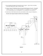
7.  Attach another length of 1-

1/2”Ø PVC Flex Hose (34) to the top end of the 1-1/2”Ø PVC Ball 

Valve (33) and run it up through the upper 1-

1/2”Ø Pipe Clamps (28) to the 1-1/2”Ø 90º Elbow 

(32).  See Figure HH. 

 
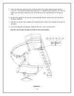
8.  When all of the connections have been made, start at the top and use PVC primer and glue to 

attach each connection securely. First place the primer on both surfaces that will be attached, 
then place the glue on the connections and slide them together. These are not provided, but can 
be purchased at any plumbing supply store. 

 
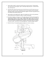
9.  After everything is assembled, use the Vulkem-116 Sealant (14) to fill in all of the galvanizing 

holes in the main section metal frame, ladder or stairway, and handrails. 

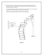
10.  The Vortex is designed to connect to a 1-

1/2”Ø water supply line. Plumb the water supply from 

the pool return line with a 1-

1/2”Ø PVC pipe.  Position the water supply “stub up” at the base of 

the slide’s ladder, where the lower end of the 1-1/2”Ø Flex Hose (28) is located.  The “stub up” 
should be installed prior to mounting the slide to the deck.  

The “stub up” should be dark grey 

PVC to match the 

slide’s plumbing assembly.  Extend the water supply “stub up” to a height of 

18” above the deck.  It can be cut to the desired length later, during the installation process. 

 
11.  A

ttach the “stub up” to the plumbing assembly installed in the slide as necessary. 


FIGURE HH 

Содержание VORTEX

Страница 1: ...HEADQUARTERS P O Box 400 1017 S W Berg Parkway Canby Oregon 97013 USA Phone 503 266 2231 Fax 503 266 4334 www srsmith com S R SMITH VORTEX SLIDES ARE MANUFACTURED FOR INSTALLATION AND USE ON INGROUND...

Страница 2: ...ASSEMBLY INSTRUCTIONS 19 VORTEX STAIRWAY PARTS LIST 22 VORTEX STAIRWAY ASSEMBLY INSTRUCTIONS 23 VORTEX LADDER PARTS LIST 32 VORTEX LADDER ASSEMBLY INSTRUCTIONS 33 VORTEX WARNING SIGN PARTS LIST 35 VOR...

Страница 3: ...TALLATION TO ENSURE THAT NO DAMAGE OCCURRED IN TRANSIT AND THAT A DAMAGED PART IS NOT USED PROPER INSTALLATION CANNOT BE OVERSTRESSED IMPROPER INSTALLATION VOIDS THE S R SMITH WARRANTY AND MAY AFFECT...

Страница 4: ...s rust or corrosion 2 All slide components require periodic maintenance Clean components with a cotton cloth and a non abrasive soap and water Avoid harsh chemicals and disinfectants 3 Always read the...

Страница 5: ...5 ASSEMBLED VORTEX WITH STAIRS LAYOUT FIGURE A...

Страница 6: ...6 ASSEMBLED VORTEX WITH LADDER LAYOUT FIGURE B...

Страница 7: ...2 ea 11 5 512 3 8 x 4 BHCS S S 8 ea 12 5 237 3 8 x 5 BHCS S S 4 ea 13 5 524 SS 1 2 x 5 HHCS S S 5 ea 14 VULKEM 116 VULKEM GRAY SEALANT 1 ea 15 05 14 132 1 2 x 1 3 8 FLAT WASHER S S 10 ea 16 05 14 115...

Страница 8: ...Seize 16 Saw to Cut PVC Pipe 17 Knife 18 Level 19 Hammer 20 8 Step Ladder 21 Rubber Mallet 22 Torque Wrench Gasket Installation The gasket material has been installed at the factory however additiona...

Страница 9: ...fasten them as shown in Figure D The required hardware is as follows 1 2 13 x 5 Hex Head Cap Screw 13 1 2 Flat Washer 15 1 2 Nylon Washer 19 and 1 2 Nylon Washer 19 1 2 Flat Washer 15 1 2 Lock Washer...

Страница 10: ...2 on the other Install the hardware through both side rails The required hardware is as follows 3 8 16 x 4 Button Head Cap Screw S S 11 3 8 Flat Washer 21 3 8 Flat Washer 21 3 8 Lock Washer 22 3 8 Hex...

Страница 11: ...nto the second branch arm to ensure proper alignment Once the assembly is in the correct position mark the locations for the main support and the exit support anchors Move the assembly aside then dril...

Страница 12: ...ant The end of each runway section is labeled and must be assembled to the runway section with the same label Assembly Tip It is recommended that Irwin Quick Grip bar clamps be used to help align the...

Страница 13: ...s and the inside edge of the part 10 Insert the Left Guard Rail 26 and the Right Guard Rail 27 into the two sockets on the top of the Entrance Section 1 as shown in Figure J so that the threaded stud...

Страница 14: ...WAY SECTION 4 ea 11 5 512 3 8 x 4 BHCS S S 6 ea 12 5 515 3 8 x 5 BHCS S S 18 ea 18 5 518 3 8 x 1 FLAT WASHER S S 48 ea 22 5 516 3 8 LOCK WASHER S S 30 ea 23 05 14 107 3 8 16 HEX NUT S S 30 ea 35 5 151...

Страница 15: ...shown in Figure K The hardware required for the two side locations is as follows 3 8 16 x 4 Button Head Cap Screw S S 11 3 8 Flat Washer S S 18 3 8 Flat Washer S S 18 3 8 Lock Washer S S 22 3 8 Hex N...

Страница 16: ...18 3 8 Flat Washer S S 18 3 8 Lock Washer S S 22 3 8 Hex Nut S S 23 Next working from the top to bottom fasten the flumes together along the outside edge as shown in Figure 12 The required hardware i...

Страница 17: ...rew S S 14 3 8 Flat Washer S S 21 3 8 Rubber Washer 27 3 8 Flat Washer S S 21 3 8 Lock Washer S S 25 3 8 Hex Nut S S 26 There are four locations where this step is repeated After you have started all...

Страница 18: ...8 x 1 OD FLAT WASHER S S 42 ea 20 05 32 111 3 8 NYLON WASHER 6 ea 22 5 151 3 8 LOCK WASHER S S 19 ea 23 5 139 3 8 HEX NUT S S 19 ea 38 05 14 151 VORTEX SPACER 5 8 X 2 75 304 SS TUBING 12 ea 39 6 690 4...

Страница 19: ...the two side locations is as follows 3 8 16 x 4 1 2 Button Head Cap Screw S S 40 3 8 Flat Washer S S 18 3 8 Flat Washer S S 18 3 8 Lock Washer S S 22 3 8 Hex Nut S S 23 Follow the same procedure to f...

Страница 20: ...8 Lock Washer S S 22 3 8 Hex Nut S S 23 Note When installing the upper Riser Bracket remove and reuse the existing hardware previously installed during the main section installation See Figure O Add...

Страница 21: ...12 3 8 Flat Washer S S 18 3 8 Custom Flat Washer S S 82 5 8 304 SS Spacer 2 3 4 38 3 8 Flat Washer S S 18 3 8 Lock Washer S S 22 3 8 Hex Nut S S 23 Tighten the hardware until the gap in the joint is...

Страница 22: ...BOLT S S 22 ea 45 5 253 SS 5 16 x 1 1 4 HEX HEAD LAG SCREW S S 42 ea 46 05 625 5 16 NYLON WASHER 50 ea 47 5 306 5 16 LOCK WASHER S S 8 ea 48 5 303 5 16 FLAT WASHER S S 58 ea 49 2022650 5 16 HEX NUT S...

Страница 23: ...s also recommended that the bar clamps be used at this point to ensure that the support remains in place Be sure that the support base plate is flat against the concrete deck Mark the hole locations f...

Страница 24: ...8 Flat Washer 21 3 8 Nylon Washer 20 3 8 Flat Washer 21 3 8 Lock Washer 22 3 8 Hex Nut 23 This should be done for both sides of the support After this connection is completed finish tightening down t...

Страница 25: ...1 2 Nylon Washer 19 1 2 Flat Washer 15 1 2 Lock Washer 16 and a 1 2 Hex Nut 17 see Figure S Note Do not fully tighten fasteners until after installing the handrails 9 Place the Inside Stair Bracket 52...

Страница 26: ...upport to the stair brackets as shown in Figure T The required hardware is as follows 1 2 x 1 1 2 Hex Head Bolt 44 1 2 Flat Washer 15 1 2 Nylon Washer 19 1 2 Nylon Washer 19 1 2 Flat Washer 15 1 2 Loc...

Страница 27: ...1 1 2 Hex Head Bolt 44 1 2 Flat Washer 15 1 2 Nylon Washer 19 1 2 Nylon Washer 19 1 2 Flat Washer 15 1 2 Lock Washer 16 and a 1 2 Hex Nut 17 Note Do not fully tighten fasteners until after installing...

Страница 28: ...e the following hardware to attach both sides of the Step Bracket Anchor 43 to the Bottom Stair Brackets 1 2 x 1 1 2 Hex Head Bolt 44 1 2 Flat Washer 15 1 2 Nylon Washer 19 1 2 Nylon Washer 19 1 2 Fla...

Страница 29: ...lot holes in the Stair Steps 57 with the holes on each side of the stair brackets as shown in Figure W Use the following hardware to attach the Stair Steps 57 to the brackets 5 16 x 1 1 4 Hex Head Lag...

Страница 30: ...ort 62 Move the stair assembly back into place with the HDPE Gaskets 71 and 72 between the base plates and deck Then reattach it to the Main Stair Support 61 and then follow the instructions on page 4...

Страница 31: ...Nut 49 see Figure Y Use the following hardware to attach the stair steps where there are not Handrail Brackets 5 16 x 1 1 4 Hex Head Lag Screw 45 5 16 Flat Washer 48 and a 5 16 Nylon Washer 46 and a 1...

Страница 32: ...ARE 4 ea 10 5 250 3 8 x 3 1 2 BHCS S S 2 ea 16 05 14 115 1 2 LOCK WASHER S S 4 ea 19 05 616 1 2 NYLON WASHER 4 ea 20 05 32 111 3 8 NYLON WASHER 2 ea 21 5 145 3 8 x 7 8 FLAT WASHER S S 4 ea 22 5 151 3...

Страница 33: ...n To ensure proper alignment of the assembly temporarily place bolts through the mounting holes in the ladder and the entrance section It is recommended that the bar clamps be used at this point to en...

Страница 34: ...the slide with the HDPE Gasket 73 between the base plate and deck Then follow the instructions on page 41 for inserting the concrete anchors into the deck The required hardware is as follows 1 2 Conc...

Страница 35: ...24 3 8 Lock Washer 25 3 8 Hex Nut 26 6 Replace the hardware for the entrance guardrail brackets that was removed during the first step of the ladder installation 7 After these connections are complet...

Страница 36: ...chors 3 Move the sign aside and drill 5 16 x 3 deep holes into the deck 4 Move the sign back into place and install the concrete anchors in accordance with the instructions on page 41 The following ha...

Страница 37: ...ain Support Tube with 8 32 x 2 Pan Head Screws 29 as shown in Figure EE Item Number Description Quantity 28 1 1 2 CLIC TOP PIPE CLAMP 5 ea 29 10 32 x 2 PANHEAD SCREW PRE INSTALLED IN MAIN SUPPORT 5 ea...

Страница 38: ...d first to ensure correct orientation before the parts are glued together 3 Slide the 1 1 2 x 3 PVC Pipe 30 into the back side of the water nozzle socket in the side of the entrance section Then assem...

Страница 39: ...39 5 Connect the 1 1 2 PVC Flex Hose 34 to the water supply Then run the other end up through the lower 1 1 2 Pipe Clamps 28 6 Attach the 1 1 2 PVC Ball Valve 33 as shown in Figure GG FIGURE GG...

Страница 40: ...116 Sealant 14 to fill in all of the galvanizing holes in the main section metal frame ladder or stairway and handrails 10 The Vortex is designed to connect to a 1 1 2 water supply line Plumb the wate...

Страница 41: ...a hammer drill and a concrete drill bit Use tape or a marking on the drill bit to ensure that the hole is drilled to the required depth Keep the drill straight and perpendicular to the deck surface w...

Страница 42: ...inimum depth of water below the exit lip of the slide shall be 3 0 and increase to 4 6 at Point A which is a distance of 4 6 from the exit lip of the slide as shown in Figure KK D A minimum depth of 4...

Страница 43: ...or diving board shall not intersect any coping or rope and float line as shown in Figure NN The minimum clearance area of a slide or diving board may intersect each other provided that they are not u...

Отзывы: