9
TRANSFORMER
I n p u t / S u p p l y L i n e V o l t a g e
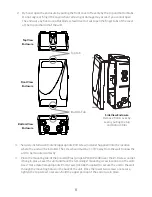
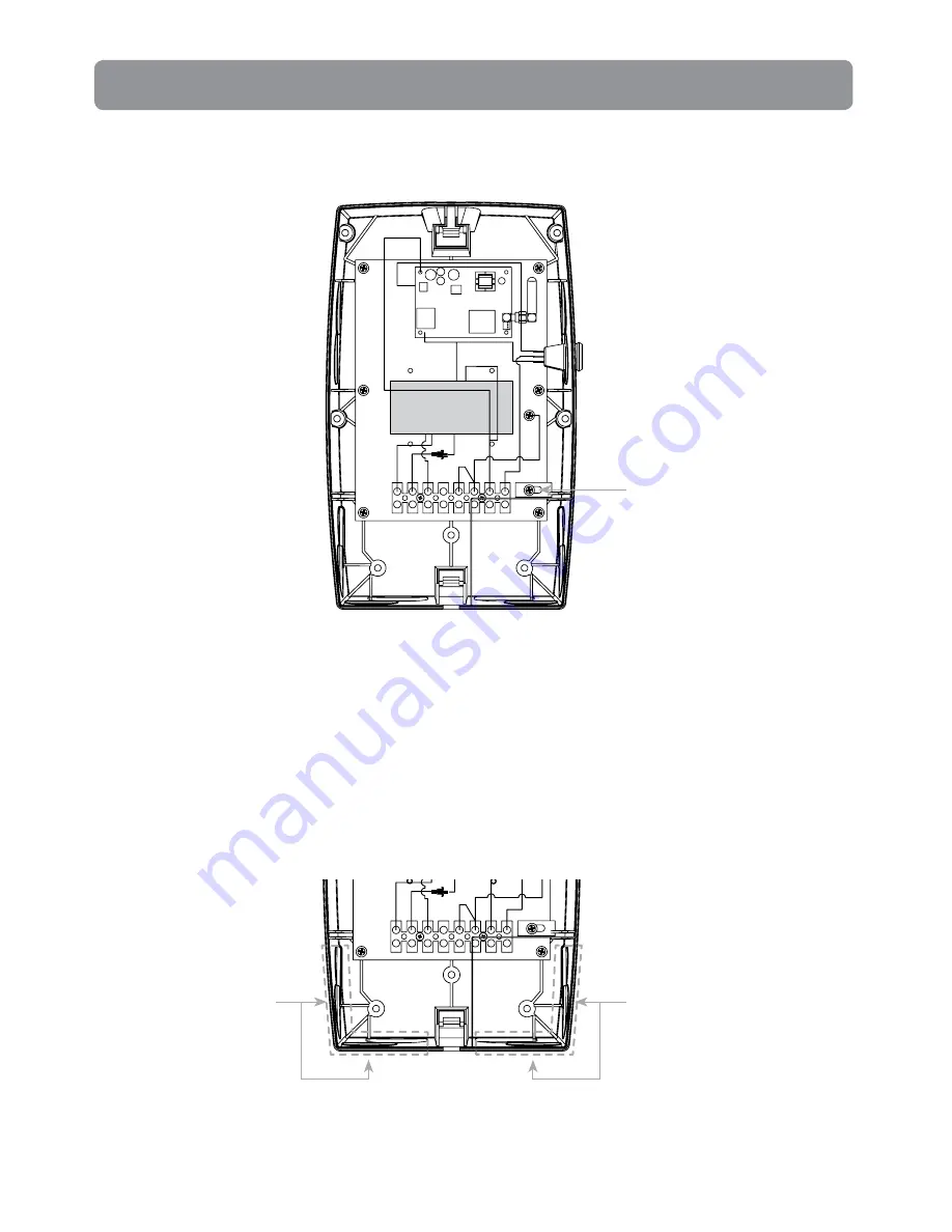
1. Remove the metal input voltage isolation barrier by unscrewing the mounting screw. Once the
securing screw is removed, the isolation cover will pull straight out to allow easier access to the
conduit knockout locations.
TRANSFORMER
Metal Input Voltage Isolation
Barrier Mounting Screw
Locations of Input
Power Knockouts
Locations of Output
Power Knockouts
*Note:
Once all conduits are connected, replace the metal input voltage isolation barrier and
mounting screw. Tighten until the mounting screw is secure.
2. Bring the supply power conduit to one of the four, lower right input power conduit knockout
locations that terminate ‘inside’ the isolation barrier. No output connections are allowed
through these knockout locations.
*Note:
The wiring of the input and output power are required to use separate conduits and
must not share an individual conduit. No conduit should contain both input and output power
wiring.
3. Using a hole saw, open the knockouts for the size of the conduit (¾" or 1") being installed.
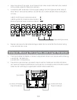
ON
OFF
REMOTE
Содержание pLX-PL60
Страница 2: ...2 ...


