background image

8

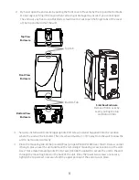
2.  By hand, open the enclosure by pulling the front cover off evenly by the top and bottom tabs. 

Do not angle or ‘hinge’ the cover when removing or damage may occur. If you cannot open 
the enclosure by hand, use a flat blade screwdriver to twist open the finger tabs of the cover 
at the top and bottom of the unit.

3.  Securely install a wall material appropriate #10 screw (Installer Supplied) into the location 

where the unit will be installed. The screw head must be 1 1/8” away from the wall to allow the 
unit to be mounted correctly.

4.  Place the mounting tab of the poolLUX Plus (p/n pLX-PL60/PL100) over the #10 screw and let 

it hang in place. Level the unit and mark the remaining 2 mounting screw locations on the wall. 
Use 2 more material appropriate #10 screws (Installer Supplied) to secure the unit to the wall 
through the mounting holes on the back of the unit. Once the lower two screws are secure, 
tighten the top screw to securely hold the upper portion of the enclosure in place.

Top View 

Enclosure

Front View 

Enclosure

Side View Enclosure

Remove front cover by 

evenly pulling the top 

and bottom tabs

Bottom View 

Enclosure

  Top Tab

  Bottom Tab

Содержание pLX-PL60

Страница 1: ...tion Instructions Read all instructions before attempting to perform installation work Type 3R Rainproof Enclosure FOR USE WITH POOL AND SPA PRODUCTS 5005508 ETL LISTED Conforms to UL STD 379 Certified to CSA STD C22 2 218 1 79 15264 00 Rev A ...

Страница 2: ...2 ...

Страница 3: ...trical Ratings 6 Recommended Tools and Supplies 6 INSTALLATION INSTRUCTIONS 7 Enclosure mounting 7 Input Supply Line Voltage 9 Output Wiring for Lights and Light Sources 10 OPERATING INSTRUCTIONS 12 Manual Rocker Switch Operation 12 Wireless Remote Operation 13 WIRING DIAGRAM 14 REPLACEMENT PARTS 15 ...

Страница 4: ...ll of the pool unless separated from the pool by a solid fence wall or other permanent barrier 3 CAUTION THE EQUIPMENT AND CONTROLS SHALL BE LOCATED NOT LESS THAN 1 M HORIZONTALLY FROM THE SPA OR HOT TUB 4 ATTENTION MAINTENIR UNE DISTANCE MINIMALE MESURÉE DANS UN PLAN HORIZONTAL DE 1 M ENTRE LA CUVE DE RELAXATION ET LES APPAREILS ET COMMANDES 5 ONLY USE COPPER CONDUCTORS 6 Do not exceed the maximu...

Страница 5: ...interference and 2 this device must accept any interference received including interference that may cause undesired operation 2 Changes or modifications not expressly approved by S R Smith LLC will void the user s authority to operate the equipment NOTE This equipment has been tested and found to comply with the limits for a Class B digital device pursuant to Part 15 of the FCC Rules These limits...

Страница 6: ...nternal Current Fuse and is designed to blow first in the event of a short and helps reduce whole transformer replacement due to field induced shorts sparking wires as well as other abnormal electrical conditions In addition this fuse is fast acting which helps protect against abnormal electrical conditions that can lead to an unsafe operating condition ONLY USE SR SMITH REPLACEMENT FUSES pLX PL60...

Страница 7: ...UX Plus p n pLX PL60 PL100 in an appropriate area that meets the following requirements a Must be mounted on a flat vertical surface b Must be a minimum of 4 inches above the ground level pool deck or higher than 8 inches above the maximum pool water level whichever provides greatest elevation c Must be positioned a minimum of 4 feet 1 2 m from the inside wall of the pool unless separated from the...

Страница 8: ...ay from the wall to allow the unit to be mounted correctly 4 Place the mounting tab of the poolLUX Plus p n pLX PL60 PL100 over the 10 screw and let it hang in place Level the unit and mark the remaining 2 mounting screw locations on the wall Use 2 more material appropriate 10 screws Installer Supplied to secure the unit to the wall through the mounting holes on the back of the unit Once the lower...

Страница 9: ...uits are connected replace the metal input voltage isolation barrier and mounting screw Tighten until the mounting screw is secure 2 Bring the supply power conduit to one of the four lower right input power conduit knockout locations that terminate inside the isolation barrier No output connections are allowed through these knockout locations Note The wiring of the input and output power are requi...

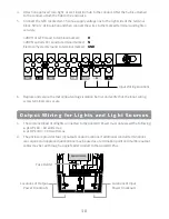
Страница 10: ...ify that the input wiring screw terminals are secure 12VAC 13VAC POWER INPUT NEUTRAL POWER INPUT POWER INPUT GROUND COM GROUND GND N H Input Wiring Locations O u t p u t W i r i n g f o r L i g h t s a n d L i g h t S o u r c e s 1 The combined load of all lights connected to the poolLUX Power must not exceed the following pLX PL60 60 watts max pLX PL100 100 watts max 2 The enclosure provides four...

Страница 11: ...onductors to the electrical taps output terminals Most installations will utilize the terminal configuration of 12VAC terminal and low voltage common terminal In some cases additional voltage may be required to operate the lights requiring use of the 13VAC terminal and the low voltage common terminal Note DO NOT use or bridge both the 12VAC and 13VAC terminal positions at the same time 7 Do a fina...

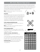
Страница 12: ...cker switch to the REMOTE position Color Changing Operation To change LED pool light colors simply toggle between the ON OFF position within 1 second of each toggle until the desired color or light show is reached Wireless Remote Operation Flip the rocker switch in the Down position or the Remote position Note Remote Operations will not work unless the rocker switch is in the REMOTE position WARNI...

Страница 13: ...command signal was sent to the control panel To Turn On Using the Wireless Remote Wake the remote out of Sleep Mode press the 1 button to turn the system ON OFF Note The rocker switch on the poolLUX Plus must be set to REMOTE for wireless operation Color Changing Operation To change pool light colors simply toggle the 1 button ON OFF within 1 second Continue toggling until the desired color or lig...

Страница 14: ...W WHITE BK BLACK B BLUE Y YELLOW G GROUND 2 ELECTRICAL CONNECTIONS LEGEND 12V 12VAC L V LOW VOLTAGE COMMON 13V 13VAC GND GROUND PI GND POWER INPUT GROUND N POWER INPUT NEUTRAL H POWER INPUT 12VAC 13VAC POWER INPUT NEUTRAL POWER INPUT POWER INPUT GROUND COM GROUND PI GND N H GND 12V L V 13V B R Y G G W W BK BK ON REMOTE OFF ...

Страница 15: ...0 44 15039 00 Transformer pLX PL100 44 15040 00 3 Way Switch 38 15002 01 Isolation Barrier 02 15342 00 Isolation Barrier mounting screw 8 32 10 15078 05 Fuse Holder 36 15016 00 Fuse pLX PL60 36 15017 00 Fuse pLX PL100 36 15018 00 RF Receiver PCB 94 15262 00 RF Remote Transmitter 94 15261 00 Antenna 5 CM 94 15265 00 ...

Страница 16: ...LC P O Box 400 Canby OR 97013 P 503 266 2231 TF 800 824 4387 srsmith com 2017 S R Smith All rights reserved 79 15264 00 Rev A Questions Contact One of Our Dedicated Lighting Specialists 1 800 824 4387 x4012 or x2282 ...

Отзывы: