Ryobi 990r, Руководство оператора
Описание продукта Ryobi 990r: Перед использованием данного устройства, обязательно ознакомьтесь с инструкцией по эксплуатации. Вы можете скачать бесплатно Operator's Manual на manualshive.com и ознакомиться с правилами безопасного и эффективного использования Ryobi 990r. Не забудьте загрузить руководство перед использованием устройства.
Поделиться
Скачать


Отзывы:
Нет отзывов
Похожие инструкции для 990r

GC-CT 18/24 Li
Бренд: EINHELL Страницы: 150

530163441
Бренд: Weed Eater Страницы: 11

EX2600
Бренд: Zenoah Страницы: 30

8060
Бренд: Efco Страницы: 20

HWT 550 TILT
Бренд: Grillo Страницы: 48

PEHA 960/3 PSB/D
Бренд: Honeywell Страницы: 6

ZW3005
Бренд: Honeywell Страницы: 4

FHS 1555 Ultralight
Бренд: Okay Страницы: 36

LTR-250
Бренд: Ozito Страницы: 14

GT3440
Бренд: Costway Страницы: 9

AHS 2020-52 Li
Бренд: Grizzly Tools Страницы: 160

LT G33
Бренд: Yard force Страницы: 16

Sabre Trim
Бренд: Flymo Страницы: 80

060-2359-2
Бренд: Yardworks Страницы: 16

PAE85T
Бренд: Virutex Страницы: 72

PAC 500
Бренд: Palmera Страницы: 14
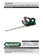
CLHT1851D
Бренд: Qualcast Страницы: 16

GLH 692
Бренд: Gardenline Страницы: 23


