background image


23.


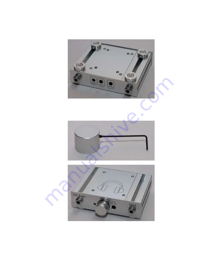
 Move the feet to the desired locations, I suggest the front feet should rest flush up against the back of the 
front panel, and the back feet should sit on or just inside the back panel as shown above and below.  After 
the screws are tightened peal off the rubber feet from the backing and install them into the recess in each 
foot.  Turn the amp right side up and press firmly down on the amp for a few seconds to make sure the 
feet are properly seated.   


24.


  Install the set screw in the volume knob, there are two knobs included in the kit allowing you to choose 
the look or feel you prefer.  With the screw still loose install the knob on the shaft of the pot, the knob 
should not be pressed tight up against the face of the amp or the knob will bind when turning.  Instead 
leave a small gap between the two allowing smooth operation.  


The amplifier is now complete. 

 Give yourself a pat on the back and prepare to test your creation.   


25.


 Insert the power plug into the connector on the back of the amp.  Plug the power supply into a suitable 
wall socket.  Turn the volume knob clockwise to turn on the amp, the green LED should illuminate.  

Содержание Amp1

Страница 1: ... required tools for assembly and testing a Soldering iron solder b Side cutter for trimming component leads c Allen keys 0 050 1 16 included 6mm not included d Hobby knife to trim LED holder e Cheap headphones for testing dollar store variety 3 Look over the entire assembly process to familiarize yourself with the steps BEFORE starting ...

Страница 2: ...40 x 3 8 Screw Board Foot mounting hardware 8 1 8 Nylon Spacer Board mounting hardware 4 4 Lock Washer Board mounting hardware 4 4 40 Nut Board mounting hardware 4 4 40 x 1 4 Screw Top Bottom panel hardware 8 M8 1 25 x 12or16 Screw Front Back panel hardware 4 Foot Retainer square nut Foot mounting hardware 4 Rubber Feet Foot protector 4 4 40 Set Screw Knob hardware 2 Enclosure Bottom Panel 8 holes...

Страница 3: ...kets Dip1 Dip3 onto the board in the IC2 IC4 locations the indent on the chip socket should match the indent shown on the board By installing all of this type of part before soldering the board will sit flat making the soldering process easier This also helps the components sit flush and tight to the board A piece of paper or card stock placed on top of the board works well to hold the parts in pl...

Страница 4: ...time It is a good idea to only solder one pad on each part at first then when all of these parts are secure confirm that each part is straight and tight to the board This is very important for proper fit to the front and rear panels 8 Install and solder IC1 C7 and C8 these are directional and must be installed as shown IC1 should sit a short distance above the board and sit straight on the board t...

Страница 5: ...ble check the solder side of the board for any poor solder connections solder bridges or parts not properly soldered to the board and fix as required The PCB is now complete Take a break and give yourself a pat on the back 12 Prepare the bottom panel as shown below Four 4 40x3 8 screws should be inserted through the inner 4 holes in the bottom panel Please note one side of the bottom panel may hav...

Страница 6: ... screws protruding through the board Do not over tighten This will compress the 1 8 spacers and possibly short out the board and miss align parts with the front rear panel holes 16 Place the two side panels about 2 inches apart and install four 4 40 x screws in the four outer holes securing the bottom panel to the sides Do not fully tighten these screws as it will allow some adjustment room for th...

Страница 7: ...ng the four remaining 4 40 x screws do not tighten 18 Install the back panel using two of the M8 screws do not tighten 19 Assemble the four amplifier feet as shown below do not tighten The square nut must be free to slide into the t slot on the bottom of the amplifier ...

Страница 8: ...ess the screw head into the pockets in the front panel as shown below There should be no gaps around these screws and the screws should not sit on the outer face of the front panel they should sink into the pockets 22 Now tighten all of the remaining screws holding the panels together in the order Top Front Bottom Back Do not over tighten the 4 40 Screws not a lot of force is required to hold them...

Страница 9: ...ll the set screw in the volume knob there are two knobs included in the kit allowing you to choose the look or feel you prefer With the screw still loose install the knob on the shaft of the pot the knob should not be pressed tight up against the face of the amp or the knob will bind when turning Instead leave a small gap between the two allowing smooth operation The amplifier is now complete Give...

Страница 10: ... assemble and test this amplifier please purchase the prebuilt version instead listed twice to make sure you are paying attention 29 If the test headphones sound good as good as they can sound anyways with no crackling distortion clicks pops and the volume control operates correctly you are finished 30 Connect your nice cans and enjoy your music of choice Amp1 will sound good right away but over 2...

Отзывы: