RUsKIn DPT-IQ FloW MeTeR WITH BaCKlIT DIsPlaY InsTallaTIon InsTRUCTIons
4
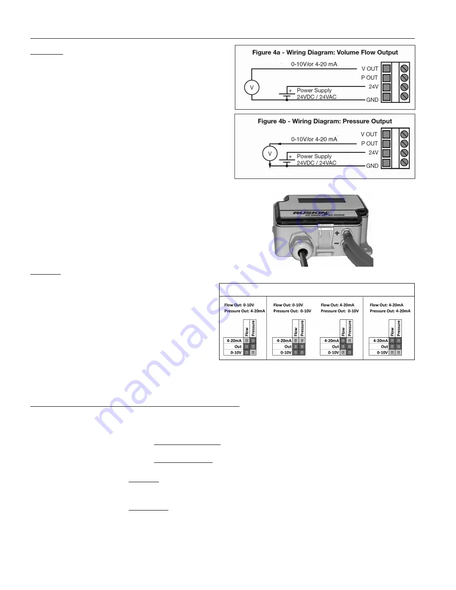
sTeP 2 WIRInG DIaGRaM
For CE compliance, a properly grounded shielded
cable is required.
1) Unscrew strain relief and route cable
2) Connect the wires as shown in figure 4a and 4b.
3) Tighten the strain relief.
application Connections
The pressure tubes are connected from the ports on
the bottom of the DPT-IQ (Figure 5) to a flow mea-
surement probe, or to the measurement station ports
as specified by Ruskin. Please see the installation
guide or the technical specifications for the specific air
measurement station.
sTeP 3 ConFIGURaTIon
To configure the Output signals (0-10V or 4-20mA) for
Pressure and Flow (Velocity or Volume), install jumpers
on the 6-pin set of Output Jumpers for Flow and Pres-
sure, located on the right side of the open device (see
Figure 3B). The configuration options for the jumpers are
shown to the right (Figure 6 jumper installed).
For 0-5V, set jumpers same as for 0-10V and change
selection in menu (Mode) to 0-5V.
ConFIGURaTIon MenU.
selection convention used to input information into DPT-IQ
Entering information into the DPT-IQ is accomplished with three (3) Menu buttons (see Figure 3B). The Menu
buttons are labeled as follows:
Button 1: SELECT. Pressing down or tilting button 1 serves two functions:
A.
Highlight Submenus: When a submenu is available, pressing down or tilting
button 1 will activate the submenu, causing it to blink.
B.
Confirm Selection: When the proper choice is shown on the screen, pressing
down or tilting button 1 will select and store that value.
Button 2: UP.
Cycle Up: Pressing down or tilting button 2, will cycle up through the menu choices.
If you cycle past your desired choice, the menu cycles through all the choices and
returns to the beginning of the list.
Button 3: DOWN. Cycle Down: Pressing down or tilting button 3, will cycle down through the menu
choices. If you cycle past your desired choice, the menu cycles through all the choices
and returns to the beginning of the list.
Push down on button 1 (see Figure 3B Schematic for location of button 1, 2, and 3) for 2-5 seconds to enter
the CONFIGURATION MENU.
Page 4 Upper Right
0-5V, 0-10V/or 4-20 mA
Figure 5 - Pressure Ports
output signal (0-10V or 4-20ma) Jumper Positions
*
*
*
*
Figure 6


