


Runco CL-810 Series Owner’s Operating Manual
65
PRE
L
IMINAR
Y
5.1
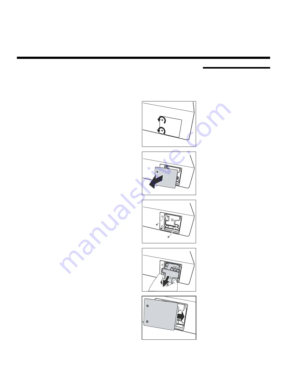
Lamp Replacement
The lamp should be replaced when it reaches the end of its life (typically 2000 hours), or
sooner if a noticeable degradation in brightness occurs. Contact your Runco dealer to
obtain a replacement lamp.
1.
Turn off the projector and unplug the power cord.
Allow the projector to cool down for
approximately 45 minute
s
prior to removing
the lamp a
ss
embly for replacement.
2.
Loosen the two captive screws from the lamp
cover.
3.
Remove the lamp cover.
4.
Remove the two lamp assembly mounting screws.
5.
Grasp the lamp assembly handle and pull gently,
removing the lamp module from the projector
housing.
6.
Install the new lamp module and replace the two
screws.
7.
Replace the lamp cover at the right side first and
secure it with the two screws.
8.
Turn on the power and select Reset Lamp Timer
from the Set Up menu to reset the lamp timer (refer
to
Reset Lamp Timer
on page 60).
5
Maintenance and Trouble
s
hooting
Содержание Reflection CL-810 / SDC-1
Страница 2: ......
Страница 10: ...Table of Contents x Runco CL 810 Series Owner s Operating Manual P R E L I M I N A R Y Notes...
Страница 12: ...List of Figures xii Runco CL 810 Series Owner s Operating Manual Notes...
Страница 56: ...Installation 44 Runco CL 810 Series Owner s Operating Manual P R E L I M I N A R Y Notes...
Страница 76: ...Operation 64 Runco CL 810 Series Owner s Operating Manual P R E L I M I N A R Y Notes...
Страница 80: ...Maintenance and Troubleshooting 68 Runco CL 810 Series Owner s Operating Manual P R E L I M I N A R Y Notes...
Страница 84: ...Serial Communications 72 Runco CL 810 Series Owner s Operating Manual P R E L I M I N A R Y Notes...
Страница 90: ...Specifications 78 Runco CL 810 Series Owner s Operating Manual P R E L I M I N A R Y Notes...
Страница 91: ......


