Copyright © 2014 Ruckus Wireless, Inc.
Published April 2014, Part Number 800-70604-001 Rev A
Page 3 of 4
S
TEP
3: A
SSEMBLING
THE
AP M
OUNTING
B
RACKET
AND
THE
AP
1
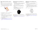
Place the AP mounting bracket (F in Figure 1) onto the back
side of the AP so that the four screw holes on the bracket
align with the four screw holes on the AP. Make sure that the
longer end of the AP mounting bracket points away from the
AP connector.
Figure 5:
Positioning the AP mounting bracket on the AP
2
Insert the 0.250-28 bolts (I in Figure 1) with washers into the
screw holes on the AP mounting bracket. Tighten the bolts to
2.5-3.0 N.m or 22-27 in-lbs.
CAUTION:
The mounting bolt length is critical. Do not use bolts
longer than the supplied 0.250-28 x 0.625” L parts or the unit may
be damaged.
3
Continue with
.
S
TEP
4: M
OUNTING
THE
AP
1
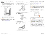
Align one of the holes on the extension bracket (E in Figure 1)
with the hole on the hanger mount.
Figure 6:
Align the extension bracket hole with the hanger mount hole
2
Insert an M8 hex bolt into hole and finger tighten until the bolt
passes through the screw hole on the hanger mount.
Figure 7:
Finger-tightened hex bolt
3
Align the hole on the mounting bracket with the remaining
hole on the extension bracket.
4
Insert an M8 hex bolt into the hole and finger tighten until the
bolt passes through the extension bracket.
Figure 8:
AP mounting
5
Adjust the azimuth and elevation of the AP as required.
6
Using a 13mm wrench, tighten the M8 hex bolts to 13.6 N.m
(10 ft-lbs) so the extension bracket is securely fastened to the
AP mounting bracket and the hanger mount.
7
Continue with
Step 5: Earth Grounding the AP
S
TEP
5: E
ARTH
G
ROUNDING
THE
AP
CAUTION:
Make sure that earth grounding is available and that it
meets local and national electrical codes. For additional lightning
protection, use lightning rods and lightning arrestors.
NOTE:
The color coding of ground wires varies by region. Before
completing this step, check your local wiring standards for
guidance.
•
Using the factory-supplied ground wire and ground screw,
connect a good earth ground to the AP chassis ground point
(A in Figure 9).
Figure 9:
Connect good earth ground to AP here
Congratulations! You have mounted your T301n access point.
T
ROUBLESHOOTING
CAUTION:
If required, you can reset the AP to its factory default
settings by pressing the reset button located inside the PoE OUT/
RESET port. DO NOT DO THIS UNLESS SO INSTRUCTED.
(Doing this resets the AP IP address to 192.168.0.1.)
NOTE:
After a reset, you can access the internal AP web interface
using
https://192.168.0.1
. Your device must use any
other address from 192.168.0.2 through 192.168.0.254, with
subnet mask 255.255.255.0 and default gateway 192.168.0.1.
The username is
super
, and the password is
sp-admin
. Refer
to the T301n 802.11ac Outdoor Access Point Installation Guide
and the ZoneFlex Outdoor Access Point User Guide for
information on configuring and operating the AP. Both documents
are available at
https://support.ruckuswireless.com
.
A


