


Copyright © 2013 Ruckus Wireless, Inc.
Page 2 of 4
Published March 2013, Part Number 800-70494-001
S
TEP
4: C
USTOMIZE
THE
W
IRELESS
S
ETTINGS
1
On the Web interface menu, click
Configuration
>
Wire-
less
(
Configuration > Radio 2.4G
or
Configuration > Radio
5G
). The Configure :: Wireless :: Common options appear.
2
Verify that the following options are active:
•
Channel
: SmartSelect
•
Country Code
: If you are not located in the United
States, select your current country.
•
External Antenna
: Enable the check box and enter
the external antenna gain in the field provided.
3
Click
Update Settings
if you made any changes.
4
Click any of the eight “Wireless #” tabs at the top of the
page.
5
In
Wireless Availability
, click
Enabled
.
6
Delete the text in the
SSID
field, and then type a name for
your network that will help your users identify the AP in their
wireless network connection application.
7
Click
Update Settings
to save your changes.
8
Repeat Steps 4-7 for each Wireless # interface that you want
to enable.
9
Click
Logout
to exit the Web interface.
10
Disconnect the AP from the computer and from the current
power source, and then restore your computer to its original
network connection configuration.
S
TEP
5: P
LACE
THE
AP
IN
Y
OUR
S
ITE
1
Move the AP to its permanent location (accessible to both
AC power and network connection).
2
Use an Ethernet cable to connect the 10/100/1000 port of
the AP to your network.
3
Connect the AC power adapter (or PoE power supply) to the
AP, then to a convenient power source.
4
Verify that the 10/100/1000 port LED is lit.
5
Connect external antennas to the RP-SMA connectors on
the 7372-E enclosure. Note that each connector is a dual-
band (2.4 GHz & 5 GHz) spatial stream.
•
Ruckus Wireless offers two different antenna kits as sep-
arately orderable accessories, certified for use with the
7372-E:
•
911-0303-VP02 (articulating direct-mount antenna
pair)
•
911-0505-DP01 (2-stream sector antenna panel)
After a short pause to re-establish the Internet connection, you
can test the AP.
S
TEP
6: V
ERIFY
THE
I
NSTALLATION
1
Using any wireless-enabled computer or mobile device,
search for and select the wireless network you previously
configured.
2
If you can connect, open a browser and link to any public
Web site.
Congratulations!
Your wireless network is active and ready for
use.
(O
PTIONAL
) M
OUNTING
I
NSTRUCTIONS
The ZoneFlex 7372-E can be mounted to a wall, ceiling or to a T-
bar using the supplied mounting screws or the T-bar clips built
into the bottom of the AP enclosure.
Mounting to a Flat Surface
1
Use this
Quick Start Guide
template or the alignment spacer
to mark the locations for screw holes on the mounting sur-
face. Use a 5mm drill bit to drill approximately 25mm into
the mounting surface.
2
Insert the anchors and mounting screws into the mounting
surface, leaving approximately 0.28” (7 mm) of the screw
heads protruding for the AP enclosure.
The screws should be approximately 3.25” (82.6 mm) apart
per the template.
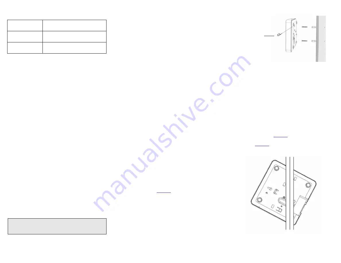
3
Insert a straightened paperclip (or similar) into the hole on
the side of the AP (
), to release the locking mecha-
nism.
Figure 1. Insert a paperclip into the pinhole
4
Place the AP onto the mounting screws so that the screw
heads enter the mounting holes on the AP enclosure, and
push the AP downward to lock in place.
5
Remove the paperclip to release the lock mechanism and
secure the AP.
6
To unmount, insert a straightened paperclip into the hole on
the side of the AP to unlock, then push the AP upward to
release the AP enclosure from the mounting screws.
Mounting to a T-Bar
The ZoneFlex 7372-E provides mounting options for flush tile
and recessed frame T-bars in acoustical ceiling tiles.
Flush Tile
1
Orient the AP so that the T-bar is positioned between the T-
bar clips as shown in
, then rotate the AP until the
third T-bar clip catches the T-bar and the latch locks the T-bar
in place (
Figure 2.
Default AP Settings (For Your Reference)
Network Names
(SSIDs)
Wireless1—Wireless8 (2.4GHz radio)
Wireless9—Wireless16 (5GHz radio)
Security (Encryption
method)
Disabled for each wireless interface
Default Management
IP Address
192.168.0.1
NOTE
:
If you will be using PoE, you will need a Cat5e (or better)
Ethernet cable to connect the AP to the PoE injector or switch.
Hold paperclip in
while mounting


