R60-IO
User Manual
-7-
szruitech.com
internal photocoupler is turned on, the driver will cut off the current of each phase of the motor to
make the motor in a free state. At this time, the step pulse is not responded.
When the motor is in an error state, the ENA input can be used to restart the drive. First remove
the fault, then input a falling edge signal to the ENA terminal, the driver can restart the power part,
and the motor excites.
The level logic of the ENA signal can be set to the opposite, and the logic is opposite to the
above.
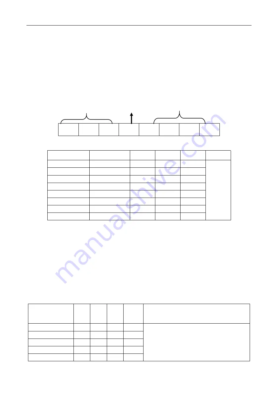
4. The setting of DIP switches and operating parameters
The setting of current
Semi / Full current option
The setting of pulse per revolution
4.1 The setting of current
Peak Current
Average Current
SW1
SW2
SW3
Remarks
1.4A
1.0A
on
on
on
Other Current
can be
custom-made.
2.1A
1.5A
off
on
on
2.7A
1.9A
on
off
on
3.2A
2.3A
off
off
on
3.8A
2.7A
on
on
off
4.3A
3.1A
off
on
off
4.9A
3.5A
on
off
off
5.6A
4.0A
off
off
off
DIP SW1, SW2, SW3 are used to set current which is output from drive to motor.
Generally, the current setting is the motor rated current. If your system has high request to the heating, please
decrease the current properly to lower the motor’s heating, but at the same time, the output torque will be
lower. If you don’t need the motor running continuous, you can increase the current to higher the torque. But be
minded that the current can not be 1.5times over than the rated current.
4.2 The setting of pulse per revolution
Stepping
count/revolution
SW5 SW6 SW7
SW8
Remarks
200
on
on
on
on
The DIP switch is turned to the Default state and
the testing software can freely change other
micro-stepping level number
400
off
on
on
on
800
on
off
on
on
1600
off
off
on
on
3200
on
on
off
on
SW1
SW2
SW3
SW4
SW5
SW6
SW7
SW8


