


RTD Embedded Technologies, Inc.
|
www.rtd.com
10
LAN24550/
LAN34550 User’s Manual
Connectors and Jumpers
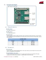
Figure 2: Board Connections
3.3.1
E
XTERNAL
I/O
C
ONNECTORS
CN3: RJ45 Connector
Port 0 twisted pair cable connector
CN4: RJ45 Connector
Port 1 twisted pair cable connector
Link and Activity LEDs
Link and activity LEDs are provided on the edges of the RJ45 connectors. The LEDs provide status information. Each is a green LED. When
the link is established, the green Link LED will illuminate on the right side of the RJ-45 connector. When there is activity on that port the green
Activity LED will blink.
Link Status LEDs
Link Speed
Left LED
Right LED
100 Mb/s
Black
Blinks Green
1 Gb/s
Green
Blinks Green
2.5 Gb/s
Black
Blinks Green
5 Gb/s
Black
Blinks Green
10Gb/s
Yellow
Blinks Green
3.3.2
B
US
C
ONNECTORS
CN16: PCI Connector
The PCI connector is the connection to PCI peripheral modules. This connector is used only as a pass through connector on this board. This
connector is not populated on the LAN34550 version.
CN1(Top) & CN2(Bottom): PCIe Connector
The PCIe connector is the connection to the system CPU. The position and pin assignments are compliant with the
PCI/104-Express
Specification
. (See PC/104 Specifications on page 18). The LAN24550/34550 is a Type 2 PCIe/104 device.
CN1 (Top)/CN2 (Bot):
PCIe Connector
CN4: RJ-45
Connector
CN3: RJ-45
Connector
CN16: PCI Connector (Pass Through)


