background image


               23


Section 4 

SERVICE INFORMATION 


4.


SERVICE INSTRUCTIONS 

4.1. 

Routine Maintenance 

4.1.1.


Daily Maintenance 

Daily  maintenance  consists  of  a  simple  series  of  functional  checks  that  will  alert 
maintenance  personnel  to  any  signs  of  developing  problems.    The  importance  of 
regularly checking the machine cannot be over stressed to prevent not only damage 
to the machine, but also loss of productive time and product.  Whenever the furnace 
is  started  up  the  failure  alarms  should  be  checked  for  signs  of  trouble.    An 
intermittent  exhaust  failure  indicates  that  something  is  wrong  and  that  the  alarm 
mechanism,  system  exhaust  fan,  and  possibly  exhaust ductwork must be checked 
and corrected as necessary.  Other alarm functions should be monitored, such as the 
lamp  failure  indicator,  to  see  if  corrective  action  is  required.    As  the  machine  is 
being started up, each control and switch should be briefly checked to insure that 
all functions are working properly.  Any controls that do not respond as expected, 
or alarms that do not clear should be checked out and corrected before putting the 
machine into operation. 

4.1.2.


Monthly Maintenance 

Monthly maintenance, in general, means four weeks of operation for one eight-hour 
shift per day.  This period of operation is not an absolute number, and it is possible 
that  some  of  the  tasks  are  needed  more  often.    Experience  with  the  machine and 
process being performed should dictate the need. 

4.1.2.1.Run a temperature profile, no less often than monthly, on machines 

that are used for sensitive processes, such as thick film firing. 

On machines that are used for a variety of products, it is advisable to set 
up a profiling schedule so that each process can be checked periodically. 
 The  most  sensitive  profiles  should  be  checked  at  least  monthly,  while 
less sensitive profiles could be checked every 2-6 months. 

Содержание 2115150301

Страница 1: ...Manual Controlled Atmosphere Infrared Oven August 28 2006 May 26 2009May 26 2009 Radiant Technology Corporation 1335 S Acacia Avenue CA 92831 5315 USA Email service radianttech com Website www radianttech com ...

Страница 2: ...209X SERIAL NUMBER 2115150301 FACTORY ORDER NUMBER 40334 RADIANT TECHNOLOGY CORPORATION 1335 South Acacia Avenue Fullerton CA 92831 5315 714 991 0200 TEL 714 991 0600 FAX http www radianttech com Near Infrared Heating Technology ...

Страница 3: ...PERATING INSTRUCTIONS 11 3 1 Power Controls and Indicators 11 3 1 1 Power Status Indicators 11 3 1 2 Controls 11 3 2 Basic Operation 12 3 2 1 Main Power 12 3 2 2 Uninterruptible Power Supply UPS ON Switch Option 12 3 2 3 Power On Startup 12 3 2 4 Fans 12 3 2 5 Furnace Log on and Initial Operation 12 3 2 6 Security and User Information 13 3 2 7 Screen Menu Located at bottom of screen 8 3 2 8 Atmosp...

Страница 4: ...eshooting 24 4 2 1 Unable to log on the OPTO22 control system does not have any power 24 4 2 2 Temperature 24 4 2 3 Conveyor System 25 4 3 Hardware Software Troubleshooting 26 4 3 1 Controller Communication 26 4 3 2 Process Problems 27 4 3 3 Abnormal sensor behavior 27 4 3 4 Remote control setup 28 4 3 5 Calibration 28 4 4 General Repair 29 4 4 1 Lamp Change Procedure 29 4 4 2 Transport Belt Repla...

Страница 5: ...on 50 7 5 1 Windows 95 Format 50 7 6 Product Viewing Area Option 51 7 7 Exhaust Stack Heater Option 51 7 8 Voltage Control Option 51 7 9 Product Sensor and On Screen Tracking Option 52 APPENDIX A DOCUMENTATION 56 Configurator 56 Channel Assignment Sheet 56 Drawings and Bills of Material 56 APPENDIX B CONTROLLER INSTALLATION 57 APPENDIX C ENGINEERING SPECIFICATIONS 58 00025 Procedure for Jumpering ...

Страница 6: ...elt Orientation 32 Figure 4 4 2 2 Belt Installation 33 Figure 4 4 2 3 Inserting Belt Splice 33 Figure 5 5 1 1 Element Monitor PLC Control 39 Figure 5 5 1 2 Element Monitor System Diagram 40 Figure 5 5 1 3 Element Monitor Status Window 41 Figure 7 3 3 1 O2 Analyzer Sampling Window 43 Figure 7 4 2 1 H2 Forming Gas Sequential Operation 44 Figure 7 5 1 1 Process Screen showing Lane Button s View Butto...

Страница 7: ...ons and custom features not found on standard production machines Each model and furnace contains many unique parts and assemblies that are not common to all In addition to the unique parts many custom features and options are routinely ordered and shipped with these furnaces In order to control and record these variations a top assembly bill of material or customer configurator has been included ...

Страница 8: ...iant Technology Customer Service Department 1 2 4 Providing Power These machines are built and tested to the voltage specified on the nameplate located adjacent to the power entrance hole in the lower electrical compartment Electrical power matching the specifications on the nameplate is to be connected to the contactor or circuit breaker located directly above the entrance hole A ground terminal ...

Страница 9: ...helpful to have an assistant available to help guide the belt into the furnace entrance 1 2 7 1 The portion of the belt which goes through the furnace is rolled up and secured at the entrance end of the furnace Unroll the belt and attach it securely to the pull wire that was left in the furnace chamber 1 2 7 2 Pull the belt through the chamber from the exit end of the furnace while an assistant gu...

Страница 10: ...nce of the furnace system Tasks to be performed by the Customer Service technician include 1 2 9 1 Prepare the machine for operation 1 2 9 2 Apply power and bring up the machine to a fully operational state 1 2 9 3 Run through the installation test procedure 1 2 9 4 Report to the customer any deficiencies noted in the installation of the machine 1 2 9 5 Instruct the appropriate personnel in the cu...

Страница 11: ...amps may become exposed to silica fiber compounds Such tasks should be performed by qualified personel wearing gloves eye protection and a facemask to prevent inhalation of particulates 2 3 Normal Good Laboratory Practice Normal good laboratory practices apply to the operation of RTC furnaces Do not use the space above the furnace as storage Do not block the cabinet doors preventing the cooling of...

Страница 12: ...rns continuously whenever power is available to the furnace and the main circuit breaker optional is turned on 3 1 1 2 ON Green Indicator This lamp burns continuously when the control circuits are energized and indicates that power is available to actuate the control circuits 3 1 2 Controls FAN CONTROL POWER CONTROLS and INDICATORS Figure 3 1 2 1 Control Panel ...

Страница 13: ...switch is located on the center front panel of the UPS 3 2 3 Power On Startup Press the POWER ON button The ON indicator illuminates Press the monitor power button The computer boots up and the logo screen is displayed CAUTION Dangerous voltages are now present throughout the electrical systems of the furnace Make sure that any probes in the furnace are placed on the belt surface only Probes exten...

Страница 14: ...Log Off through Security screen 3 2 6 1 Access Level Select Access Level by clicking on the User List then log on with the appropriate password The system is shipped with three 3 access levels each with its own password Figure 3 2 6 1 Security Window Log on Access Level 1 password 1 This is the Operator level and allows the operator to load and run a recipe and initiate a process Initial password ...

Страница 15: ... belt speed Initial password is set to 2 Access Level 3 is restricted to RTC personnel only 3 2 7 Screen Menu Located at bottom of screen Allows operator to select the desired screen by moving the cursor and clicking on the chosen screen 3 2 8 Atmosphere Supply Gas If the furnace has flowmeters turn on the atmosphere supply gas and adjust the inlet regulator to 70 psi Figure 3 2 8 1 Gas Flow Windo...

Страница 16: ...rating on hydrogen understand the appropriate features before attempting operation 3 2 8 2 Optional Mass Flow Controller S Flowmeters labeled as MFC provide control to mass flow controllers Use the vertical Slide switch or numeric dialog box on the appropriated Mass Flow Controller to set the desired flow rate ...

Страница 17: ...r to proceed with furnace operation If alarm alert does not clear see Troubleshooting Section 3 2 3 2 9 2 Verify correct recipe is loaded If not click on RECIPE icon for Recipe screen 3 2 9 3 In Process field select Warm Up to initiate the process selected In the Warm Up mode the heating elements will come on After 10 minutes check the system for instability or cycling and correct if necessary See...

Страница 18: ...r on the moving belt and time through two fixed points while the furnace is in the off or cooldown mode 3 2 11 Power Off Before pressing POWER OFF the furnace must be in cooldown mode Press the POWER OFF button Under normal conditions the furnace will turn off when all zones cool below 100o C If POWER OFF is pressed while the furnace is in the warmup or ready mode the furnace will remain in normal...

Страница 19: ...tion 3 3 1 Recipe Setup Screen Off Line Edit NOTE When editing this screen the process is not changed Level 1 access will allow the operator to inquire select and run preset parameters and recipes Level 2 access will allow the operator to edit and save recipe data When initializing the Load Run field the process screen is updated and the Recipe Setup screen is changed to On Line Edit Figure 3 3 1 ...

Страница 20: ... to calculate the power and limit it to this value NOTE The edge heaters are not part of the calculation The total power will then always stay below the number set by the user WARNING This may cause the machine to never reach the ready state since the user value may not be high enough to reach the desired temperature For example setting a maximum of 30 kW will most likely not be enough to reach a ...

Страница 21: ...crease in the gain reduces the amount of temperature deviation required to turn the heating elements on at full distributed power or decrease it Too small a value will cause the system to be sluggish in response Too high a value will cause the system to overshoot and be unstable 3 5 3 2 Integral and Derivative Default value is 6 00 Integral and 0 00 Derivative NOTE The integral or Reset function c...

Страница 22: ...1 2 and 3 The settings are in percent of maximum output power Typical setting is between 60 and 70 for product cooling Some models have a manual control at the operator control panel interface 3 7 Alarm Status All Levels This is a display only feature Any existing alarm conditions such as transport speed error are highlighted on the Process screen To clear or silence an alarm alert move the cursor...

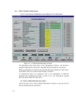
Страница 23: ...22 Figure 3 8 1 1 Event Logging ...

Страница 24: ...he machine is being started up each control and switch should be briefly checked to insure that all functions are working properly Any controls that do not respond as expected or alarms that do not clear should be checked out and corrected before putting the machine into operation 4 1 2 Monthly Maintenance Monthly maintenance in general means four weeks of operation for one eight hour shift per da...

Страница 25: ...ance is required When any Maintenance Item has timed out reached the maintenance required date the MAINT status box on the Process Window will Flash As Maintenance Items are completed click on the appropriate Completed pushbutton the Maintenance Window in order to set a new maintenance required date that is based upon the days field 4 1 3 2 User Defined Maintenance Items The lower twelve rows of t...

Страница 26: ...d from firing processes The stacks should be cleaned as necessary with a brush and solvent to remove the buildup A periodic inspection of the stacks is essential to establish a sensible maintenance cycle since some processes will require frequent cleaning and others require none at all 4 1 3 4 Check Optional Mass Flow Controller Zero Output after 6 months of operation Furnace Mode OFF mode and wit...

Страница 27: ... 3 7 1 Remove the top removable sections from the furnace 4 1 3 7 2 Remove the tray and baffles NOTE Some machines may require removing a cooling fan assembly 4 1 3 7 3 Clean the trays with a suitable solvent 4 1 3 7 4 Inspect the furnace insulation above the drip trays and gently scrape or knock loose any materials that have collected there 4 1 3 7 5 Inspect the furnace walls and lamps for contam...

Страница 28: ... be lubricated every 6 months with RTC P N 100523 chain lubricant or an equivalent all purpose chain lubricant The chain tensioner is equipped with a grease fitting for lubrication The chain tensioner should be lubricated every 6 months with a general multipurpose bearing grease Apply enough grease to the tensioner so that excess grease can be visually seen squirting out along the shaft of the dev...

Страница 29: ...the furnace It is best to make these adjustments in small increments Adjustments that are too large will cause a belt tracking problem in the other direction At the exit end of the furnace the transport motion sensor will also have to be loosened and moved with the belt shaft to maintain engagement with the gear on the belt shaft Now run the belt at its highest speed and observe how the belt is tr...

Страница 30: ...an be set at 450 C and the oven can be put into a self cleaning cycle for about an hour to burn out these organic residues 4 2 Troubleshooting To troubleshoot follow all suggestions sequentially to determine cause of problem 4 2 1 Unable to log on the OPTO22 control system does not have any power A Check fuse FB in safety enclosure box Ref Power Control Schematic in Documentation Section B Check t...

Страница 31: ...ue A The SCR needs calibration See Maint screen for details Ref Engineering Specification 00028 in Documentation Section B The SCR has failed and shorted Replace SCR 4 2 2 3 Zone temperature fluctuates A The SCR needs calibration B Improper flowmeter setting s C Adjacent zone temperature differentials are too large D Improper PID setting s NOTE The following are factory typical settings Gain 30 In...

Страница 32: ...en seen problem is no communication between the computer and the controller This is characterized by pound signs on the screen where you should have temperature or the date or any type of data Check the following things in this order Log Event Viewer Any event happening between the computer and the controller is logged on this screen You can access it by ALT TAB The following are messages that are...

Страница 33: ... SCR is out of calibration most likely it will not be noticeable in the medium range of the temperature Only at low temperature 100 C or near the maximum temperature will there be deviation from the setpoint See the SCR Calibration procedure in the Documentation Section 4 3 3 Abnormal sensor behavior There are numerous sensors standard and optional on the furnace from thermocouple to a board count...

Страница 34: ...mocouples The thermocouples come pre calibrated They do not require any additional calibration 4 3 5 4 PID tuning NOTE This procedure should only be attempted by qualified personnel Unreasonable PID parameters can stress the components of the system and cause premature failure of some electrical systems If you notice unstable behavior in a certain zone follow the following procedure to retune the ...

Страница 35: ...e too long Never set Derivative to more than one fourth of Integral time Sluggish response is caused by Gain too low Integral too long or Derivative too short The PID values will work over a rather wide range of temperature However on a High Temperature furnace the PID might require tuning for the low range of temperature around 200 C and different set of parameters around 900 C The machines are s...

Страница 36: ...ment lead wire with one wrench while removing the top nut with the other wrench Do this at one end of the element only 4 4 1 3 Use an ohmmeter and verify that the lamp filament is open If the element is bad remove the nut and washers Note that one cannot determine in general if an element is bad by visually inspecting the element with power applied or by an ohmmeter in circuit check 4 4 1 4 Remove...

Страница 37: ...en the lead emerges use it to gently work the lamp through In tight situations a dowel or stiff wire can be used The lead wire is taped to the dowel or stiff wire When inserted through to the opposite side the lamp can be gently led through by the dowel or stiff wire 4 4 1 9 Pack material between the lamp and ceramic on both ends of the lamp Be careful not to allow the packing material to cover th...

Страница 38: ...ntrance end of the furnace and orient as shown below Figure 4 4 2 1 Belt Orientation 4 4 2 2 Extend a long rod or stick through the furnace chamber being careful not to damage the lamps or insulation If possible use the old belt to draw a pull wire through the chamber during its removal Securely attach the leading edge of the belt to the rod Carefully pull the belt through the furnace from the exi...

Страница 39: ...shown below Figure 4 4 2 3 Inserting Belt Splice 4 5 Element Test Procedure This procedure is to be used to test for open heating elements 4 5 1 Required Equipment 1 Continuity Tester Ohmmeter preferred 2 3 8 Box or Open End Wrench 3 Control Element Wiring Schematic 4 5 2 Test Procedure NOTE It will be helpful to have an assistant available when performing these tests 4 5 2 1 Procedure ...

Страница 40: ...ing the resistance across the terminations of the lamp If the resistance is less than 10 ohms the element is good If resistance is greater replace the element following the procedure in section 3 3 of the manual Next check the bottom half of the zone in the same manner After verifying the top and bottom lamps replace the bus bars on the proper terminals and securely tighten all hardware Following ...

Страница 41: ...rgy absorption is increased Just as the penetrating power of x rays is greater than that of visible light so also is the penetrating power of near infrared greater to a smaller degree than that of far infrared It is precisely because of these characteristics i e the greater temperature difference existing between the radiant heat source and the part and the increase in penetrating power photon mom...

Страница 42: ...t on cooling rates The cooling module should be adjusted to provide cooling rates consistent with high yield and throughput 5 5 Solder Fusion Die Attach and Sealing Processing In general these process operations involve components which are sensitive to time at temperature and exposure to atmosphere impurities The ability to rapidly and linearly bring a unit to a temperature substantially below pr...

Страница 43: ...oading ahead of the systems being processed to bring the furnace to a stable condition is most desirable and is also determined by trial and error Atmosphere requirements are process dependent and should be adjusted to provide proper flow direction for volatile removal if any and for atmosphere composition to control any adverse effects of atmosphere on the product at temperature ...

Страница 44: ...43 Section 6 PRODUCT SPECIFICATION 6 PRODUCT SPECIFICATION ...

Страница 45: ...return RTC Furnace Operations to the active window 7 2 Element Monitor Option To select the Element Monitor Status Screen move the cursor and click on the Maint pushbutton On the Maintenance Window click on the Element Monitor pushbutton to activate the Element Monitor status window This is a display only screen which details the current status of the IR elements Element strings are displayed for ...

Страница 46: ...e Input information is transmitted back the system controller for processing alert notification and display The Element Monitor Window provides active element status displays For each element leg displayed the following status information is provided 1 8 Module rack identification a First Board element sensors 1 32 b Second Board element sensors 33 64 c Third Board element sensors 65 96 2 I O modu...

Страница 47: ...gure 5 5 1 3 Element Monitor Status Window 7 3 Moisture and Oxygen Analyzer System Option 7 3 1 Introduction This option provides a moisture and oxygen analyzer system The Oxygen analyzer is a Delta F Type A unit which uses an electro chemical cell to measure oxygen concentration The cell used in this analyzer features a non depleting electrode design which does not require periodic maintenance Th...

Страница 48: ...lyzer system is used the manufacturer s manuals should be thoroughly read and understood The oxygen and moisture analyzers are set up at the factory to operate automatically when the furnace is turned on The oxygen or moisture analyzer output is displayed on the Process window within the computer control software 7 3 3 2 Computer Control and Sample Port Selection 7 3 3 2 1 Sample Port Selection Th...

Страница 49: ...y increase momentarily until the new sample line is cleared of any residual oxygen air This momentary rise in oxygen level may cause an oxygen level alert After selecting the new sample location the oxygen level should peak and then begin to decrease rapidly within a matter of seconds If the oxygen level exceeded the alert level and does not begin to rapidly decrease within 60 seconds any hydrogen...

Страница 50: ...rge cycle for more than a total of sixty seconds To change the value of the oxygen level alarm or alert limits click the appropriate alarm alert value and type in the desired high value 7 4 Hydrogen Operation Option 7 4 1 Introduction The hydrogen operation option is designed to provide a means of introducing a reducing atmosphere into the furnace Because hydrogen is an extremely flammable gas and...

Страница 51: ...ate an inert gas curtain which effectively keeps ambient air from entering the furnace chamber and mixing with the hydrogen atmosphere Venturi assisted exhaust stacks located in the entrance baffle or in both entrance and exit baffles draw off the excess hydrogen and direct it into a burner assembly The excess hydrogen which is drawn through the exhaust stack is directed into the burner where it i...

Страница 52: ...ut off and the hydrogen cycle is aborted with alarm and display indication Only after nitrogen pressure is restored can the cycle be restarted 7 4 2 1 2 Hydrogen Pressure Hydrogen pressure must be present during the purge cycle and during straight hydrogen operation In the event of hydrogen failure the cycle is aborted and nitrogen flow is initiated with an alarm and display indication Only after ...

Страница 53: ...rator to possible injury 7 4 4 Operating Instructions OPTO22 Control System 7 4 4 1 Process Screen Controls and Indicators Hydrogen Atmosphere Go to Process screen and click on H2 Button Click on Warm Up Wait until the process start light is flashing and click on Process Start This starts an automatic timed purge with nitrogen and lasts from 5 to 30 minutes When the purge cycle is complete click o...

Страница 54: ...age and an audible alarm If both igniters in a single stack fail the hydrogen operation cycle is aborted and cannot be restarted until the igniters are repaired If only one igniter fails in a single stack the process is not aborted but an alert occurs 7 4 5 Hydrogen Flowmeters Each of the hydrogen flowmeters is identified with a label as to specific function and is adjustable from zero flow to ful...

Страница 55: ...trace oxygen analyzer The oxygen concentration can vary considerably depending on flow settings but as long as 100 ppm or less is maintained in the furnace combustion will not occur If the concentration of oxygen is above the 100 ppm limit increase the flow of helium in small increments and retest the oxygen level Allow several minutes between gas flow corrections and oxygen testing for the analyz...

Страница 56: ...turn the furnace to nitrogen operation Adjust the nitrogen volume to the values calculated in 2 12 6 6 Shut off the hydrogen flowmeters Select the hydrogen atmosphere mode and select the nitrogen hydrogen mix mode before the purge cycle is complete Then adjust the hydrogen flowmeters The machine should now be operating in a balanced condition with the proper volume of nitrogen hydrogen Check the o...

Страница 57: ...provided The remote operator in conjunction with on site personnel can simultaneously view the Process screen and have access to input and control features 7 5 1 Windows 95 Format A Click on Start bottom left hand corner of screen B Select Programs and highlight C Select PcAnywhere 32 and highlight D Select PcAnywhere and double click with touchpad trackball E Select Be A Host PC and click highlig...

Страница 58: ...ing the exhaust stack The heater has a power control that is set at the computer The customer can specify the number and location of heaters 7 8 Voltage Control Option Voltage Control means manual control of the power applied to the lamp by the operator by manually entering the percentage of power in each of the zone power fields When Voltage Control is installed a check box is visible on the main...

Страница 59: ...em to automatic mode WARNING Manual voltage control at the maximum temperature setting for the furnace may result in over temperature and damage to the equipment 7 9 Product Sensor and On Screen Tracking Option The purpose of the product sensor and on screen tracking feature is to count the number of product units travelling through the furnace A set of sensors at the entrance and exit detect the ...

Страница 60: ...ick the recipe button on the process screen Once in the recipe screen shown in Figure 0 2 double click the product length box A pop up window labeled Send Value will appear Define the product unit length in the product length window and click OK ...

Страница 61: ...presentations of the defined product unit length will scroll this screen at the set belt speed The number of units which have entered the furnace will appear in the ENTR column The number of units processed through the furnace will appear in the EXIT column The number of units still in process will appear in the INSIDE column Click on the Clear Product Counts button to reset the count to zero Figu...

Страница 62: ...61 View Product Tracking ...

Страница 63: ...of Materials and Schematics Listing for Electrical Electronics Bill of Materials for Mechanical Electrical Schematics Power Control Schematic Frame Wiring Schematic Signal Control Schematic Options Schematics Element Wiring Schematic Drawings Installation Drawing Transport Drawing ...

Страница 64: ...t started exit The first time the controller is turned on its memory is empty and the software has to be downloaded Double click on the download icon in the radiant group in Windows This will download the kernel the Operation System for the controller and the RTC software and start running it You can now start the MMI software by double clicking on the Furnace icon From now on startup will be auto...

Страница 65: ...e for Jumpering Analog I O and Expansion Cards for OPTO 22 00028 SCR Power Control PCB Calibration OPTO 22 Control System 00034 Calibration Procedure for Motor Speed Controller Board and Conveyor Belt OPTO 22 00042 Ethernet Installation and Troubleshooting ...

Страница 66: ...r proper operation addressing baud and loop back jumpers See figure 1 for jumper location on brain board 2 1 ADDRESSING Every I O or Analog card brick needs a unique address Card or Brick JP 1 numbe r 7 6 5 4 3 2 1 0 0 0 0 0 0 0 0 0 0 1 0 0 0 0 0 0 0 X 2 0 0 0 0 0 0 X 0 3 0 0 0 0 0 0 X X X JUMPER INSTALLED 4 0 0 0 0 0 X 0 0 0 NO JUMPER INSTALLED 5 0 0 0 0 0 X 0 X 6 0 0 0 0 0 X X 0 7 0 0 0 0 0 X X ...

Страница 67: ...sion card brick must have the expansion cable attached to the brain card NOTE No jumpers required See figure 2 for expansion cable installation 9 ORIGINATOR ALEX REY 10 DATE 7 29 96 PAGE ISSUED Lee Lablin DATE 1 OF 2 radiant technology corporation ENGINEERING SPECIFICATION ES NO 00025 REVISIO NS A 11 APPROV AL Local SERVO Control Brick Brain FIGURE 5 11 1 Expansion Board ...

Страница 68: ...ery six months to ensure proper furnace operations 3 1 Zero Crossing Adjustment The zero potentiometer has both positive and negative voltages available By turning the zero control clockwise the unit s output voltage will increase proportionately to the adjustment Turning it counterclockwise will decrease it 3 2 Span Adjustment The span potentiometer is used to adjust the maximum output It will ad...

Страница 69: ... setting possible with the LED still flashing 3 6 Click on Stop 3 7 Click on Done 15 ORIGINATOR Alex Rey 16 DATE September 16 1996 PAGE ISSUED DATE 1 of 2 W public PUBLIC Engineering Specifications 00034 doc 6 25 01 radiant technology corporation ENGINEERING SPECIFICATION ES NO 00028 REVISIONS 16 1 A 16 2 17 APPROVAL 3 8 Span Set all zones and edge heats to 0 power 3 9 Set the true RMS voltmeter t...

Страница 70: ...ay be necessary to repeat adjustments 3 0 through 3 10 18 ORIGINATOR 19 DATE PAGE ISSUED DATE 2 of 2 radiant technology corporation ENGINEERING SPECIFICATION ES NO 00034 REVISIONS 19 1 B 19 2 20 APPROVAL Alex Rey CALIBRATION PROCEDURE FOR MOTOR SPEED CONTROLLER BOARD AND CONVEYOR BELT OPTO 22 1 0 SCOPE This document is intended to describe the configuration of the motor control board and calibrati...

Страница 71: ...mined by referring to the chart 2 2 Direction switch CLOSE CW OPEND CCW See figure 1 for switch location 2 3 The motor control board is designed to operate on a nominal 120 VAC 50 or 60 Hz If a 50 Hz source is used jumper J5 on the main control board must be cut See figure 1 for jumper location 3 0 PROCEDURE FOR BELT CALIBRATION a Set the transport speed to half the maximum transport speed b Calcu...

Страница 72: ...EVISIONS 22 1 B 22 2 23 APPROVAL Alex Rey Model 3911C FIGURE 4 CONTROL CIRCUIT BOARD DETAIL 24 ORIGINATOR 25 DATE PAGE ISSUED DATE 2 of 3 radiant technology corporation ENGINEERING SPECIFICATION ES NO 00034 ...

Страница 73: ...VISIONS 25 1 B 25 2 26 APPROVAL Alex Rey CONTROL CIRCUIT BOARD DETAIL FIGURE 4 CONTROL CIRCUIT BOARD DETAIL ISSUED DATE 3 of 3 TOC 1 INTRODUCTION 6 2 GENERAL SAFETY GUIDELINES 10 3 OPERATING INSTRUCTIONS 11 ...

Страница 74: ...ORIGINATOR ALEX REY 70 22 DATE 03 08 00 70 23 APPROVAL 71 24 ORIGINATOR 71 25 DATE 71 26 APPROVAL 72 27 SETUP OF WINDOWS PC ETHERNET INTERFACE 73 28 RESET AND ASSIGN AN IP ADDRESS TO THE LCM4 CONTROLLER S ETHERNET CARD 76 29 TROUBLESHOOTING WINDOWS SETUP OF ETHERNET CONNECTION 78 30 VERIFY THAT THE EXTERNAL OPTO22 SNAP LCM4 CONTROLLER S JUMPERS ARE CONFIGURED CORRECTLY 80 27 Setup of Windows PC Et...

Страница 75: ... on the Network dialog box Select the TCP IP Ether component 27 2 6 Then on the TCP IP Properties for FastEtherLink Dialog Box Select the Specify an IP Address Bullet Enter the following IP Address 10 192 105 100 and Subnet Mask as 255 255 255 0 then click Ok 27 2 7 On the Re boot system Dialog Box Select NO 27 2 8 On the Network Dialog box select the Identification TAB 27 2 8 1 Change the Compute...

Страница 76: ...ws desktop Double Click the My Computer Icon then Right Click The C disk drive icon 27 2 11 1 On the pull down menu Select Sharing 27 2 11 2 On The C Properties Sharing Dialog box Select the Shared As Bullet then Select Ok Note Leave all other item to their default setting Name C Read Only ...

Страница 77: ... and handling the card 28 1 1 Remove Ethernet and RS 232 connectors 28 1 2 Release 4 front panel set screws and 2 covers 28 1 3 Remove Card from chassis 28 2 Move the J7 Jumper to the Module Reset Position as shown in the following diagram 28 3 Reinstall the M4SENET 100 card into the Opto22 controller box 28 4 Apply power to the system Note The power switch on the PC may need to be initialized Set...

Страница 78: ...ing and then turn remove power from the system Note This procedure resets the Opto22 Ethernet Card to its factory default settings 28 5 After removing power from the system again remove the M4SENET card and restore the J7 Jumper to its normal position as shown below ...

Страница 79: ...0 28 12 Click on the Send pushbutton to assign the entered address 28 13 The Data Window should now be updated to display a Yes under the Sent Column 28 14 Click on Exit to leave the Opto BootP application 29 Troubleshooting Windows Setup of Ethernet Connection 29 1 Click on the Start button 29 2 Select the Settings menu 29 3 Select the Control Panel folder 29 4 Find Select and Open the Network ic...

Страница 80: ...menu 29 8 Click the Properties button 29 9 Click on the IP Address tab 29 10 Check to make sure the Specify an IP address selector switch is marked 29 11 If not select and set the following IP Address 10 192 105 100 Subnet Mask 255 255 255 0 29 12 Click the OK button ...

Страница 81: ...80 30 Verify that the external Opto22 SNAP LCM4 controller s jumpers are configured correctly Jumper the following E R B1 AUTO B2 XO B3 X1 A0 Figure 30 1 LCM4 External Jumpers ...

Страница 82: ...81 Appendix D Material Safety Data Sheets Kaowool Magnaform Duraboard High Purity Fibers High Purity Papers Cements RTV Silicone Red Hi Temp ...

Страница 83: ...82 ...

Отзывы: