Real Time Automation, Inc.
27
1-800-249-1612
Configuring Read and Write Scan Lines
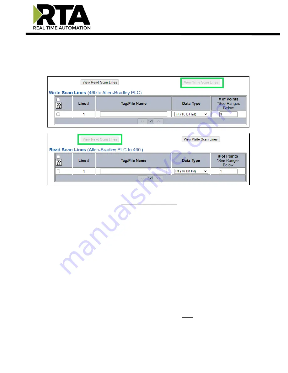
Follow these steps to manually configure Read and Write Scan Lines.
1)
Click the
View Read Scan Lines
or
View Write Scan Lines
button.
2)
Enter the
Tag/File Name
that is set up within the PLC. If you are trying to access a tag that is defined
in the Program Scope, please see the Access Program Scope Tag section below.
NOTE:
If you are
ONLY
using Write Scan Lines, then the RTA gateway will not connect to the PLC
until we receive valid data from the source. It’s recommended yo
u use
Unconnected
messaging so
when the RTA gateway sends data to the PLC, we only send it once and close the connection until a
Change of State. Leaving it at Connected messaging, once we receive data, the RTA gateway will
constantly be writing to the PLC to maintain that connection.
a)
If you wish to start from a point other than the base, add [#] to the end of the Tag/File Name to
specify which point is the starting point.
i)
Example:
A tag called “ReadTag” has dimension of 100 in the PLC. By default, we wil
l start
at point 0 of that array. Therefore, “ReadTag” and “ReadTag[0]” refer to the same point. To
start from a different point, such as array index 27, enter in “ReadTag[27]” as the Tag/File
Name in the gateway’s scan line. This means the gateway will go
to “ReadTag” and start at
array index 27.
ii)
If you wish to access a specific bit from any data type, you
must
use the Mapping Page’s Set
Bit math function.
You may
not
use ReadTag/0.0 to access bits.


