116
Input/output patchbay
Input/output patchbay
c.
Patch symbol
A patch symbol is shown where the currently patched channel
and jack intersect. To change the patching, move the cursor to
the location where the desired channel and jack intersect, and
press [ENTER].
You can make user preference settings to specify whether or not
a confirmation message appears when you attempt to change
the patching. For details, refer to “Editing the name of user
settings” (p. 174).
d.
Unavailable jack area
The number area is shown in gray for jacks that cannot be used
with the currently connected input/output unit.
The function buttons perform the following operations.
1.
In the setup section of the top panel, press [PATCHBAY].
The PATCHBAY screen will appear.
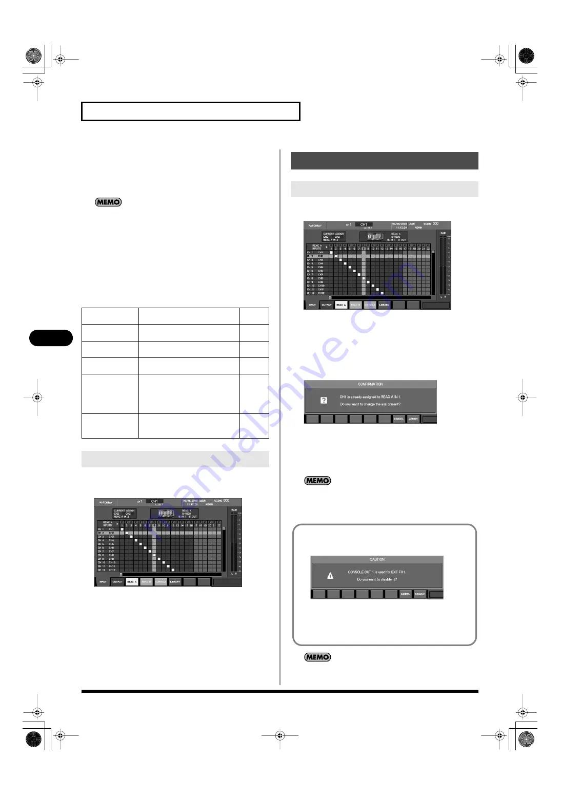
fig.ScrPatchIn1608.eps
1.
Access the PATCHBAY screen.
fig.ScrPatchIn1608.eps
2.
Press [F1 (INPUT)] to access the INPUT tab.
3.
Press [F3 (REAC A)], [F4 (REAC B)], or [F5 (CONSOLE)] to
select the desired location for the input jack.
4.
Move the cursor to the intersection of the desired channel
and jack, and press [ENTER].
fig.ScrPatchInChgConf.eps
If an input port is already patched to the channel, a message
will ask you to confirm the input patching change.
Press [F8 (ASSIGN)] to change the input patching.
If you press [F7 (CANCEL)], the input patching change will be
cancelled.
If the “PATCHBAY CHANGE” item in the CONFIRMATION
section of User Preference (p. 177) is unselected, no confirmation
message will appear in step 4.
A maximum of 40 input jacks each can be handled for the REAC
A port and the REAC B port, respectively.
[F1 (INPUT)]
Displays the INPUT tab, where
you can set the input patch bay.
[F2 (OUTPUT)]
Displays the OUTPUT tab, where
you can set the output patchbay.
[F3 (REAC A)]
Allows you to make patch bay set-
tings for the REAC A input jacks.
[F4 (REAC B)]
Allows you to make patch bay set-
tings for the REAC B input jacks.
[F5 (CONSOLE)]
Allows you to make patch bay set-
tings for the M-400’s rear panel in-
put/output jacks, and for internal
ports such as the effect output and
the USB memory recorder output.
[F6 (LIBRARY)
Accesses the IN PATCHBAY LI-
BRARY or OUT PATCHBAY LI-
BRARY popup.
Accessing the PATCHBAY screen
Input patchbay operations
Editing the input patching
If you attempt to patch a CONSOLE IN that an EXT FX is using,
a caution message such as the following will appear.
fig.ScrInPatchExtFx.eps
Press [F8 (DISABLE)] to disable the corresponding EXT FX and
continue with the patching change.
If you press [F7 (CANCEL)], the patching change will be
cancelled.
M-400_v15_e.book 116 ページ 2008年6月20日 金曜日 午後4時5分
Содержание M-400
Страница 247: ...MEMO M 400_v15_e book 247 ページ 2008年6月20日 金曜日 午後4時5分 ...
Страница 248: ...MEMO M 400_v15_e book 248 ページ 2008年6月20日 金曜日 午後4時5分 ...
Страница 249: ...MEMO M 400_v15_e book 249 ページ 2008年6月20日 金曜日 午後4時5分 ...
Страница 250: ...For EU Countries For China M 400_v15_e book 250 ページ 2008年6月20日 金曜日 午後4時5分 ...


