


PEARL Owner's Manual
13
RSF Woodburning Fireplaces
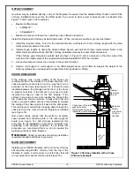
CEILING CLEARANCE
Ceiling clearance is the distance from the base of
the fireplace to the ceiling. Under no
circumstances should the distance between the
ceiling firestop and the base fireplace be less
than the dimension specified in Table 1 (C).
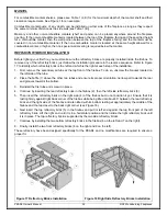
STANDOFF INSTALLATION
Before you begin installing your fireplace, you
MUST install the standoff provided on the top of
the fireplace.
The back shield MUST be open on the back side
as shown at the top of Figure 6. You can then
install the standoff on the fireplace as shown in
Figure 6 with the screws provided in the manual
bag.
DO NOT fill the gap between the fireplace and the
standoff with insulation or any other material; it
will be covered with the finishing material.
NOTHING CAN BE PLACED BELOW THE
HEADER SUPPORTS OF THE TOP STANDOFF
WHETHER COMBUSTIBLE OR NOT. THE
SPACE MUST REMAIN EMPTY.
SECURING THE FIREPLACE IN PLACE
Once the fireplace is in its final location, take the
time to attach it to the floor. Using at least two of
the five small brackets that were securing the
fireplace to the crate, attach the casing of the
fireplace to the floor. If possible, try to have at
least one, if not two, of the brackets screwed into
the floor joists with 2" wood screws.
OUTSIDE AIR DUCT
After the fireplace is correctly positioned, connect the
outside air inlet to the fireplace.
Use an insulated aluminium flexible duct rated at over
200° F. The duct should not exceed 12' vertical rise
above the base of the unit. We suggest using the 4"
RSF outside air kit (FO-INT).
The air inlet should be at least 5' below the top of
the chimney flue and must never terminate in attic
spaces.
A 4" diameter duct can be used if the total duct run is
less than 25'. For longer runs, use 5" diameter duct.
Both 4" and 5" connecting sleeves are provided with
the fireplace.
1. Find a convenient location for the insulated flexible
duct and outside air inlet. The outside air inlet can
be above or below floor level (see Figure 7).
2. Make a 4 ¼" (5 ¼" if using a 5" diameter duct)
hole in the outside wall of the house. Push the
Examples of the position of the framing with
respect to the top stand-off
Figure 6 Standoff Installation
Figure 7 Outside Air Connection and Installation
Example
Above Floor
Example
Below Floor
Example
RS
F
Fi
re
pla
ce
RS
F
Fi
re
pla
ce
RS
F
Fi
re
pla
ce
2" Aluminium
Duct Tape
Insulated Flexible Air Duct
Outside Wall
Outside Air
Inlet


