RS PRO HS-608 Скачать руководство пользователя страница 13

13/08/2017 Version No. 001


 MeterScope/English

 MeterScope/English

13/08/2017 Version No. 001

23

22

5-27.Changing Meter Setup Options

The Meter has a number of preset features such as date and time formats and battery save mode 

timeouts, and the displayed language. These variables are referred to as Meter setup options. 
Many setup options affect general Meter operations and are active in all functions. Others are 
limited toone function or group of functions.

Access to the setup options is always available through the 
softkey labeled Setup. Information about the Meter, such as 

serial number, model, for example. is also accessed
through the setup menu.

5-28.Resetting Meter Setup Options

The Meter’s setup options can be reset to default values through the setup menu. Open the 
setup menu by pressing the softkey labeled Setup. Position the menu selector next to the menu 

item labeled Reset and press the softkey labeled Setup. A message will appear asking to 

confirm the reset action. Press the softkey labeled OK to perform the reset.
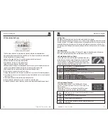
5-29.Meter Info

The Meter Info selection lists the serial number, model number, firmware version, calibration 
date, and calibration counter. Operator name, company name are  displayed.

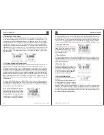
5-30.Setting the Event Threshold Value

Press the softkey labeled Setup to access the setup menu.

Using the cursor buttons, move the menu selector next to the menu item labeled Instrument 
and press the softkey labeled Enter to open the recording setup screen. Using the cursor 

buttons,move the menu selector next to the menu item labeled Event Threshold for Recording
(AutoHOLD) and then press the softkey labeled Edit. Press     or     to scroll through the event 
threshold values. With the desired value selected, press the softkey labeled Close.


5-31.Calibration

password that allows the Meter to be calibrated.
Press the softkey labeled Setup to access the setup menu. Using the cursor 
buttons, move the menu selector next to the menu item labeled Calibration and 

press the softkey labeled Calibrate, Then input password ,Enter Calibration menu.
If change password, Press the softkey labeled Setup to access the setup menu. 

Using the cursor buttons, move the menu selector next to the menu item labeled 
Calibration and press the softkey labeled password, Then input current password, 
Then input new password.

The Calibration selection allows a qualified calibration technician to enter a 

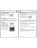
5-33.Setting Date and Time

The Meter’s internal clock is used in the display and for timestamping recorded measurements. 

To change the date and time as well as the display format, press the softkey labeled Setup. 

Position the menu selector next to the menu item labeled Display. To set the date and time, 
press the softkey labeled Date/Time to open the date/time menu. Next, position the menu 

selector next to either the Set Date item or Set Time item and press the softkey labeled Edit.
Using      and     , position the cursor on the date or time element to adjust.Use      and      to 

change the selected date or time element value. Press OK to complete the action.

5-34.Auto Power Off

Press the softkey labeled Setup. Position the menu selector next to the menu item labeled 

Display. To set Auto Power Off and then press the softkey labeledEdit. Use      and      to adjust 
the time to one of the preset values. 0 is disable the timeout feature. Press the softkey labeled 
OK to set the selected time. Press the softkey labeled Close to return.

5-35.Setting Format

Press the softkey labeled Setup. Position the menu selector next to the menu item labeled 
Format. Using thecursor buttons, move the menu selector next to the menuitem labeled 
Numeric(Date\Time) format, press the softkey labeled EDIT, select 0.0000(0,0000) and MM/

DD/YY(DD/MM/YY) and 24 HOUR (12 HOUR) format.

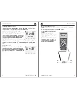
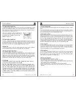
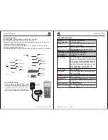
5-36.Replacing the Batteries

Refer to Figure  and replace the batteries as follows:

1.Turn the Meter off and remove the test leads from the terminals.

2.Remove the battery door assembly by using a standardblade screwdriver to turn the battery

   door screw one-half turn counterclockwise.

3.Replace the batteries with 7.4 volt charge batteries Observe proper polarity.

4.Reinstall the battery door assembly and secure it by turning the screw one-half turn 

   clockwise.

5-32.Using Communications

Y

ou can use the Wireless communication link and transfer the contents of a meter’s memory 

to a PC.
Press the softkey labeled Setup to access the setup menu. Using the cursor buttons, move the 
menu selector next to the menu item labeled communicate and press the softkey labeled 

ENTER

press the softkey labeled

OK

will start communications function.


Содержание HS-608

Страница 1: ...0001 China www rs components com Europe RS Components Ltd PO Box 99 Corby Northants NN17 9RS United Kingdom www rs components com Japan RS Components Ltd West Tower 12th Floor Yokohama Business Park 134 Godocho Hodogaya Yokohama Kanagawa 240 0005 Japan www rs components com U S A Allied Electronics 7151 Jack Newell Blvd S Fort Worth Texas 76118 U S A www alliedelec com South America RS Componentes...

Страница 2: ...cates that a device is protected throughout by double insulation or reinforced insulation PER IEC1010 OVERVOLTAGE INSTALLATION CATEGORY OVERVOLTAGE CATEGORY I Equipment of OVERVOLTAGE CATEGORY I is equipment for connection to circuits in which measures are taken to limit the transient overvoltages to an appropriate low level Note Examples include protected electronic circuits 2 Safety MAX 1 Introd...

Страница 3: ...st acting fuse 20A for 30 seconds max every 15 minutes 1000VDC AC rms 1000VDC AC rms Input Protection Limits Function V DC or V AC mA AC DC A AC DC Frequency Resistance Capacitance Duty Cycle Diode Test Continuity Temperature Surge Protection 8kV peak per IEC 61010 OVERVOLTAGE CATEGORY II Equipment of OVERVOLTAGE CATEGORY II is energy consuming equipment to be supplied from the fixed installation ...

Страница 4: ...d function is shown The secondary display contains the bar graph and values that may be measured in addition to the primary function value For example with frequency measurement selected in Vac the frequency value will appear in the primary display with the ac voltage value in the secondary display 4 5 Softkey Labels Labels for the four function softkeys F1 through F4 appear in the bottom row of t...

Страница 5: ...enough to contact the live parts inside some 240V outlets for appliances because the contacts are recessed deep in the outlets As a result the reading may show 0 volts when the outlet actually has voltage on it Make sure the probe tips are touching the metal contacts inside the outlet before assuming that no voltage is present CAUTION Do not measure AC voltages if a motor on the circuit is being s...

Страница 6: ...e current reference value Pressing or scrolls through the nine predefined references 4 8 16 25 32 50 75 600 and 1000 Set the reference by pressing the softkey labeled OK 5 4 Low Pass Filter The Meter is equipped with an ac low pass filter When measuring ac voltage press the soft key labeled Menu to open the function menu and move the menu selector to the LO item Next press the softkey labeled LO t...

Страница 7: ...l through the numbers for each digit in the offset or switch between a or offset With the desired value displayed press the softkey labeled OK to set the temperature offset 5 7 Frequency Measurements 1 Set the function switch to the green Hz position 2 Insert the black test lead banana plug into the negative COM jack Insert the red test lead banana plug into the positive V jack 3 Read the Frequenc...

Страница 8: ...ug into the negative COM jack Insert the red test lead banana plug into the positive jack 4 If the resistance is less than approximately 25Ω the audible signal will sound If the circuit is open the display will indicate OL 5 10 Diode Test 1 Set the function switch to the green Ω CAP position 2 Press the soft key labeled Menu Move the menu selector to the menu item labeled Diode Press the soft key ...

Страница 9: ...d the capacitance value in the Display 5 12 DC Current Measurements CAUTION Do not make 20A current measurements for longer than 30 seconds Exceeding 30 seconds may cause damage to the meter and or the test leads 1 Insert the black test lead banana plug into the negative COM jack 2 For current measurements up to 5000µA DC set the function switch to the yellow µA position and insert the red test le...

Страница 10: ... primary measurement function rotary switch position has a number of optional sub functions or modes accessed by pressing the softkey labeled Menu F1 A typical menu is shown in Figure Menu selection is indicated by the filled in black square hereafter the menu selector to the left of a menu item Use the four front panel cursor buttons to position the menu selector next to a menu item As the menu s...

Страница 11: ...appear in the secondary display with their respective elapsed times To stop a MIN MAX recording session press the softkey labeled Stop The summary information in the display freezes and the softkeys change function to allow saving the collected data Pressing the softkey labeled Close exits the MIN MAX record session without saving the collected data To save the MIN MAX screen data the MIN MAX sess...

Страница 12: ...11 5 25 Recording Measurement Data The Meter s record feature collects measurement information over a user specified duration This collection of information is called a recording session A recording session is made up of one or more measurement records Each record contains measurement summary information covering the duration of the record Press the softkey labeled Save Position the menu selector ...

Страница 13: ...t to the menu item labeled Calibration and press the softkey labeled password Then input current password Then input new password The Calibration selection allows a qualified calibration technician to enter a 5 33 Setting Date and Time The Meter s internal clock is used in the display and for timestamping recorded measurements To change the date and time as well as the display format press the sof...

Страница 14: ...arge symbol in TFT color LCD display Adapter Socket 6 General Specification Double molded waterproof 6 5 feet 2 meters Test current of 0 9mA maximum open circuit voltage 3 2V DC typical Audible signal will sound if the resistance is less than 25Ω approx test current 0 35mA Captures peaks 1ms Requires type K thermocouple 10MΩ VDC 9MΩ VAC True RMS The term stands for Root Mean Square which represent...

Страница 15: ...smission power Minimum 18dBm to 4 dBm Diameter 20 0mm High 3 2mm Typical Weight 3 0 grams 0 10 oz Designation ANSI NEDA 5004LC IEC CR2032 Normal Voltage 3 0 Volts Typical Capacity 240 mAh Storage 5 Year Chemical type Lithium polymer Standard GB T 18287 2000 Normal Voltage 7 4 Volts Charge up Voltage 8 4 Volts Typical Capacity 2400 mAh Cycle life 500 times 7 Specifications Function DC Voltage Range...

Страница 16: ...000Hz 1 0 25 1 5 40 Function AC Voltage 5000 Count Range 500mV 5V 50V 50mV Resolution 0 01mV 0 0001V 0 001V 0 001mV Accuracy 5K 100K 5 0 40 6 0 40 NOTE Accuracy is stated at and less than 75 RH AC switch according to the calibration of sine wave It generally increase 2 reading 2 full scale if non sine wave in the wave crest less than 3 0 18 to 28 C 65 to 83 F Function Resistance Range 1 50Ω 1 500Ω...

Страница 17: ...RMS Resolution 0 001Hz 0 01Hz 0 0001kHz 0 001kHz 0 01kHz 0 0001MHz 0 001MHz 0 01 0 001kHz Accuracy 0 01 10 0 5 reading Function Duty Cycle Range 0 1 to 99 90 Pulse width 100µs 100ms Frequency 5Hz to 150kHz Resolution 0 01 Accuracy 1 2 reading 2digits Function Temp type K Range 50 to 1000 C 58 to 1832 F Resolution 0 1 C 0 1 F Accuracy 1 0 reading 2 5 C 1 0 reading 4 5 F Probe accuracy not included ...

Страница 18: ...r A charger according with user s country standard CD pc software General safety requirements Know the following safety precautions to avoid personal injury also to prevent damage generated by connecting this product to any other product In order to avoid any potential danger please use the product according to these instructions Only qualified technical personnel can perform maintenance procedure...

Страница 19: ...pe provides a simple but with clear function front panel to make sure the convenience of basic operation to user The front panel includes 4 function keys F1 F4 4 direction keys 4 selection keys HOLD MODE AUTO REC user can enter into different functional menus or directly obtain specific function applications by using these keys Picture 1 1 operation panel Picture 1 2 interface display 1 Date and t...

Страница 20: ...uto search key search waveform of unknown frequency or amplitude REC record key record current waveform content the length is 10 pages direction key adjust sample rate preselecting amplitude and etc 2 2 Connector The probe and connector must be used when the measuring frequecies above 1KHz When measured waveform signal of DC or measuring frequency is below 1KHZ the stick of general oscilloscope ca...

Страница 21: ... waveform 2 8 1 Trigger Mode 2 kinds of trigger mode for the oscilloscope raising edge and falling edge When signal voltage across trigger electrical level raising and falling edge of input signal is adopted for triggering Raising edge setup press setup trigger raising edge save and quit Falling edge setup press setup trigger falling edge save and quit If select setup trigger no trigger save and q...

Страница 22: ...ive value and frequency unit Hz Under FFT interface press F2 or F3 according to prompt bar to move red cursor corresponding frequency and relative amplitude can be measured Picture 2 10 1 split screen Picture2 10 2 Note DC component or deviation existed in signal may cause error or deviation in FFT waveform component part Select DC coupling mode to reduce AC component Nyquist frequency for wavefor...

Страница 23: ...r more than 1 second for fast move the cursor moves continuously in the same direction 2 Press MODE to switch left right cursor lighter cursor indicates state of activation 3 Display mode of frequency and cycle is also switched at the time of left right cursor switch Activate left cursor displays frequency right cursor for cycle See picture 2 11 1 Picture 2 10 1 Picture 2 10 2 4 Press F1 V F curso...

Страница 24: ...m displaying state turn back to waveform displaying state 3 This chapter mainly introduces several application examples these simplified examples focus on some main functions of the oscilloscope and user may take it for reference to solve some actual testing problems Simple measurement Cursor measurement Analyze detailed information of signal Analyze communication signal difference by mathematical...

Страница 25: ... wave and harmonic wave 3 5 Waveform Save Waveform data save should be operated under static state three ways lead to static state 1 Press HOLD F2 SAVE 2 Press REC F2 SAVE 3 Press FFT HOLD F1 SAVE Then operate according to screen prompts Fault Processing 4 1 General fault processing 1 The Li ion batter 1 If the screen goes black please try one of the following y may be out of charge please recharg...

Страница 26: ... To avoid device or probe damage any abradant reagent or chemical cleaning reagent can not be adopted Before cleaning the device please make sure to disconnect all lines Daily maintenance Appendix 2 Specifications Function LCD display Refresh rate Bandwidth Input Input impedance Max input voltage Probe attenuation Sampling mode Real time sample rate Sampling resolution Record length Storage length...

Страница 27: ...about visualization datalog sharing and data management and it needs to combine with Digital Multimeter for proceeding to the measurement 1 Wirelessly remote measure voltage current resistance and capacitance electric parameters 2 The measured data from Digital Multimeter can transfer to APP via bluetooth and visualize store and log 3 The measuring data can be shared with others With Meterbox iMM ...

Отзывы: