background image

7

WARNING:

 This fan must be use the RF wall control. 

Can not indicate other speed control or the like.

WARNING:

 To reduce the risk of electric shock, this

fan must be installed with an isolating general-use

wall control / switch.

RECEIVER

TO MO

TOR(PINK)

TO MO

TOR(GREY)

TO MO

TOR(RED)

FOR LIGHT

 NEUTRAL(WHITE)

FOR LIGHT

 LIVE(BLUE)

BLACK

WHITE

YELLOW/GREEN

BLACK(TO MOTOR)

BLACK(TO AC L)

GREEN GROUND

OUTLET

BOX IN CEILING

GROUND TO

HANGER BRACKET

AND DOWNROD

FAN

LIGHT

WH

WH

BLUE

BK

Magnet ring

(Don’t remove)

RF WALL 

CONTROL

MAKING ELECTRICAL CONNECTIONS

DO NOT USE THIS DC MOTOR FAN IN 

CONJUNCTION  WITH ANY VARIABLE 

(RHEOSTAT) WALL CONTROL OR 

REMOTE CONTROL.

VIEW AFTER INSTALLATION

RF ANT

RECEIVER

Lock protection -

   The DC motor has a build-in safety 

feature against blade or motor obstruction during operation.


If something obstructs the fan blades or motor, the motor 

will keep trying to run and then stop operation after about 

20-30 seconds of interruption.  Remove obstacles and 

use RF wall control included with this fan.

The DC fan receiver provides protective functions.

Over load protection (current limit) -

 The device limit 

the maximum current output from the receiver/drive 

when the fan load was increased abnormally.

Refer to wiring diagram making correct wire connections.

NOTE: 

This fan must be installed by a licensed electrician.

After wire connections have been made, turn leads upward 

and carefully push the white wire and black wire connections 

into the outlet box. The other connections should be spread 

apart neatly and place on both side of the hanger bracket.

WARNING:

 Check to see that all connections are tight, 

including ground connection. 

DO NOT

 operate fan until 

the blades are secured in place.

Содержание 1070W

Страница 1: ...1070W 1080W For Models Installation Guide Net Weight Of 1070W Fan 30lbs 13 7kgs Net Weight Of 1080W Fan 35lbs 15 9kgs...

Страница 2: ...ELECTRICAL CONNECTIONS 6 8 7 10 11 12 13 13 9 9 TROUBLESHOOTING CARE OF YOUR FAN OPERATING YOUR FAN MOUNTING OPTIONS HANGING THE FAN STANDARD CEILING INSTALLATION CANOPY ASSEMBLY ATTACHING THE FAN BLA...

Страница 3: ...1 Do not use water or detergents when cleaning the fan or fan blades A dry soft cloth or lightly dampened cloth will be suitable for most cleaning lbs 32kgs ft 3M SAFETY RULES...

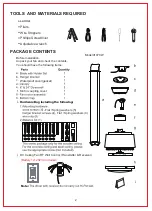
Страница 4: ...contents You should have the following items DC Ceiling Fan RF Wall Control Transmitter Receiver s j a b c d e f g h Motor coupling cover Hardware Bag including the following Pliers Note Battery 1x12...

Страница 5: ...RF Wall Control Transmitter Receiver s i j Motor coupling cover Hardware Bag including the following Note Battery 1x12V23A Included OFF ON FAN OFF 1 2 5 4 3 5 Flat Spring washers 5 Flat Spring washers...

Страница 6: ...Fig 2 Fig 3 Fig 4 Ceiling joists Ceiling Secure the outlet box directly to the building structure Use appropriate fasteners and building materials To reduce the risk of fire electric shock or persona...

Страница 7: ...n in Fig 5 Step 4 Route wires and safety cable exiting from the top of the fan motor through the canopy coupling cover and then through the ball downrod Fig 6 Step 6 Tighten two set screws on top of t...

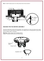
Страница 8: ...proof Cover Hanger bracket HANGING THE FAN MOTOR ASSEMBLY Lift the fan assembly onto the mounting bracket Then will allow you to make the electrical connections Ensure the notch of the ball joint is p...

Страница 9: ...inst blade or motor obstruction during operation If something obstructs the fan blades or motor the motor will keep trying to run and then stop operation after about 20 30 seconds of interruption Remo...

Страница 10: ...ET with the CANOPY Ensure that all electrical wiring is carefully tucked inside the canopy Locate 2 screws on underside of mounting bracket Attach canopy to the mounting bracket by placing screws into...

Страница 11: ...taching fan blades Remove the 4 screws and washers on fitter plate and fix the bottom cap on using these screws and washers Fitter plate Bottom cap Screws Step 1 Fasten each blade assembly to motor by...

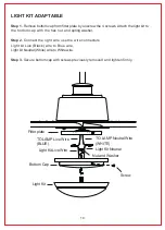
Страница 12: ...sher Step 2 Connect the light wire use the wire connectors Light kit Live Black wire to Blue wire Light kit Neutral White wire to White wire Step 3 Secure bottom cap with screws previously removed and...

Страница 13: ...operate the fan normally The buttons on the wall transmitter control the fan speed and light as follows Forward Reverse Press this button to get desired airflow direction It will take a few seconds f...

Страница 14: ...cooling effect as shown in Fig 7 This allows you to set your air conditioner on a warmer setting without affecting your comfort Cool Weather Reverse An upward airflow moves warm air off the ceiling a...

Страница 15: ...witch wire connections in the switch housing Make sure all motor housing screws are snug Make sure the screws that attach the fan blade bracket to the motor hub is tight Make sure wire nut connections...

Страница 16: ...RP 100919...

Отзывы: