background image

21 

• 

To light the side burner place the lighted end of a long match alongside the side burner. Push and 
turn the side burner control knob anti-clockwise to the high position taking care to protect yourself 
from flames. 


CARE AND MAINTENANCE 


n

Do not leave the barbecue uncovered and exposed to the elements when not in use. Heavy duty 
covers are available from your Royal stockist. Even when your barbecue is covered for its protection, 
it must be inspected on a regular basis as damp or condensation can form which may result in 
damage to the barbecue. It may be necessary to dry the barbecue and the inside of the cover. Any 
rust that is found that does not come into contact with the food should be treated with a rust inhibitor 
and painted with barbecue paint or a heat resistant paint. Chrome plated warming racks etc. should 
be coated with cooking oil. 
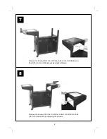
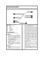
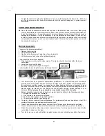


Burner Assembly 


To remove the burners (see photos): 
1.  Remove the burner clip. 
2.  Lift the burner upwards. 
3.  Gently pull the burner mouth away from the valve injector. 
4.  Lift the burner out and remove the cardboard packing. 
 
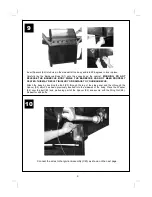
To re-install the burners (not depicted): 
1.  Slide the burner mouth over the valve injector. The injector should sit centrally within the burner 

venturi tube. 

2.  Lower the burner into the body. 
3.  Insert the locating stud through the support. 
Lock into place by inserting the burner clip through the stud 


• 

Your burners have been preset for optimal flame performance. You will normally see a blue flame, 
possibly with a small yellow tip when the burner is alight. If the flame pattern is significantly yellow, 
this could be a problem caused by grease from cooking blocking the burner or spiders or other 
insects in the burner venturi. This can result in the flow of the gas and air mixture being restricted or 
blocked which may result in a fire behind the control panel causing serious damage to your 
barbecue. 

If this happens, the gas should be immediately turned off at the bottle.


• 

Burners should be inspected and cleaned on a regular basis in addition to the following conditions: 
1.  Bringing the barbecue out of storage. 
2.  One or more of the burners do not ignite. 
3.  The burner flame pattern is significantly yellow. 
4.  The gas ignites behind the control panel. 

• 

To clean a burner, remove it from the barbecue. It is quite normal for a cast iron burner to rust. The 
outside of the burner can be cleaned with a wire brush. 

• 

Clean the portholes with a pipe cleaner or piece of wire. Take care not to enlarge the portholes. 

• 

Clean the insect screen on the end of the venturi tube with a bristle brush (i.e. an old toothbrush). 

• 

Clean the venturi tube with a pipe cleaner or piece of wire. You may need a torch to see into the 
venturi tube to make sure it is clear. 

• 

Turn the burner up on end and lightly tap against a piece of wood to dislodge any debris from inside.
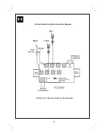


Injectors  locate  into 
the central hole of the 
burner venturi tube. 

Venturi 

Содержание 359

Страница 1: ...ctions may be dangerous and will invalidate your warranty This does not affect your statutory rights Retain these instructions for future reference Leak test annually and whenever the gas bottle is removed or replaced FOR YOUR SAFETY If you smell gas 1 Shut off gas to the appliance 2 Extinguish any open flame 3 Open barbecue lid or hood 4 If odour continues discontinue use and contact your local d...

Страница 2: ...y 1 B7 Drip Pan 1 B8 Foil Liner 1 B9 Briquette Basket 2 B10 Briquettes 2 B11 Griddle 1 B12 Grill 2 TROLLEY C1 Side Burner 1 C2 Side Burner Grill 1 C3 L H Side Burner Shelf with Lid 1 C4 Tool Hook 1 C5 R H Side Shelf 1 C6 Towel Rail 1 C7 Hose 1 C8 Regulator 1 C9 L H Panel 1 C10 Divider 1 C11 R H Panel 1 C12 Top Panel 1 C13 Back Panel 1 C14 Bottom Panel 1 C15 L H Door 1 C16 R H Door 1 C17 Door Handl...

Страница 3: ...pecifications subject to change without prior notice For more details on hardware please see Hardware Reference Diagram A6 A4 A3 A5 B11 B12 B9 B10 D1 C5 C2 D4 B6 B8 B7 B4 B5 C9 C11 C8 C15 C20 A1 A2 B3 B1 C1 C3 C4 C6 C12 C7 C24 C13 C14 C18 C16 C17 C21 C22 C23 D3 D2 D5 D6 C19 B2 ...

Страница 4: ...Reference Diagram Specifications subject to change without prior notice Part E1 22pcs E2 22pcs Part E3 Bolt 8pcs Part E4 Washer 8pcs Part E5 Spacer 8pcs Part E6 Wing Nut 8pcs Part E8 4pcs Part E7 4pcs Part E1 6pcs ...

Страница 5: ...ternal packaging before commencing assembly All loose items including the grills griddle briquette baskets and warming basket must be removed from the body Whilst every care is taken in the manufacture of this product care must be taken during assembly in case sharp edges are present 1 Attach the L H Panel C9 to the Bottom Panel C14 using the Screws E1 and Nuts E2 Attach the R H Panel C11 to the B...

Страница 6: ...6 Attach the Top Panel C12 to the L H C9 and R H C11 Panels with the Screws E1 and Nuts E2 Attach the Support C24 between the Top and Bottom Panels using the Screws E1 and Nuts E2 L H R H L H C24 3 4 ...

Страница 7: ...7 Attach the Back Panel C13 to the assembled portion of the cabinet using the Screws E1 Screw the Casters C19 into the L H Panel and the Lockable Casters C20 into the R H Panel L H R H L H R H 5 6 ...

Страница 8: ... Screws from the L H Panel Attach the L H Side Burner Shelf C3 to the L H Panel by replacing the Screws Remove the Screws from the R H Panel Attach the R H Side Shelf C5 to the R H Panel by replacing the Screws 7 8 ...

Страница 9: ...ERLY SEATED THIS MAY RESULT IN INJURY OR DAMAGE TO YOUR BARBECUE Attach the body by inserting the Bolt E3 through the leg of the side panel and then through the Spacer E5 which has been previously inserted into the sidewall of the body Place the Washer E4 over the bolt E3 and protruding part of the Spacer E5 and secure with the Wing Nut E6 Repeat for all 8 bolts Connect the wires to the Ignition A...

Страница 10: ...10 Cuisine Electronic Ignition Assembly Diagram Connect the wires as shown in the diagram Black 9V Battery Included Black Yellow Blue Ignition Pushbutton Side Burner 11 ...

Страница 11: ... E2 Insert the gas hose C7 through the hole to the inlet of main manifold Ensure the mating faces of the connection are clean and not damaged Do not use any sealing tape paste or liquid on the joint The nut must be tightened with the use of a spanner Do not use force which may damage the assembly 12 13 ...

Страница 12: ...essing the spring pins and placing into the Cabinet Connect the gas hose C13 to the side burner valve of side Burner Shelf Ensure the mating faces of the connection are clean and not damaged Do not use any sealing tape paste or liquid on the joint The nut must be tightened with the use of a spanner Do not use force which may damage the assembly 14 15 ...

Страница 13: ...o the R H Side Shelf using the Screws E1 and Nuts E2 Remove the plastic wrap from the Briquette Baskets B9 and lay them into the body ensuring that they lie level within the body Lay the Grills B11 and Griddle B12 into place 4 6 Burner Configuration Left two thirds Grills Briquette Baskets Right third Griddle 16 17 ...

Страница 14: ...erie Motor D4 to the R H Bracket Place the Forks D2 onto the Spit Rod D3 and insert the Spit Rod into the Slot in the Motor Attach the L H and R H Brackets D5 D6 to the Barbecue Body using the Screws E7 and Nuts E8 18 19 ...

Страница 15: ...g the barbecue For details of leak testing please refer to instructions on Page 19 Slide the Drip Tray B6 into place underneath the barbecue body Place the Foil Liner B8 into the Drip Pan B7 and slide into place Number of gas valves to be tested may vary according to model of barbecue 20 21 ...

Страница 16: ...ked 3 Slide one of the spit forks onto the spit rod and tighten its thumb screw to secure it into place Insert the pointed end of the spit rod into the meat being cooked and slide the meat towards the centre of the rod Make sure the fork is fully into the meat Slide the other fork onto the rod into the meat and tighten the thumb screw once in place For optimal rotisserie cooking food must be place...

Страница 17: ...ers to the high setting for 3 5 minutes to pre heat the barbecue This should be done before each session When pre heating is complete cooking can begin taking extra care if the burners are used in the high position To prevent food sticking we recommend that you use a long handled brush to apply a light coat of cooking oil to the grills and griddles before each barbecue session Side Burner Open the...

Страница 18: ...ldren tamper with bottles IMPORTANT INFORMATION For use with LPG bottled gas only A fixed pressure regulator of 28 mbar must be used for butane or 37mbar for propane The use of an adjustable regulator is dangerous and must never be used with this barbeque This product is for outdoor use only Do not use indoors Do not use below ground level as LP gas is heavier than air so if a leak occurred the ga...

Страница 19: ...ers instructions The casters should always have the brakes on when the barbecue is in use LEAK TESTING Always perform a leak test in a well ventilated area Step 1 Confirm all control knobs are in the off position Step 2 Detach the barbecue control panel located across the front of the barbecue body by pulling off the control knobs and removing the control panel retaining screws Step 3 Turn on the ...

Страница 20: ...en food is barbecued as fat and juices fall onto the ceramic briquettes Some fat is necessary to give the food its barbecued flavour but excessive fat can result in a flare up To avoid flare ups it is advisable to trim excess fat from meat and poultry before grilling use cooking sauces and marinades sparingly and try to avoid very cheap cuts of meat or meat products as these tend to have high fat ...

Страница 21: ...r clip through the stud Your burners have been preset for optimal flame performance You will normally see a blue flame possibly with a small yellow tip when the burner is alight If the flame pattern is significantly yellow this could be a problem caused by grease from cooking blocking the burner or spiders or other insects in the burner venturi This can result in the flow of the gas and air mixtur...

Страница 22: ...nd dry Door handles Side burner Do not use abrasives Stainless Centre of hood Wipe with a cloth wrung out in hot soapy water Doors A stainless steel cleaner may be used if required Side burner lid Shelf insert Control panel Galvanised Drip tray Excess fat and food debris must be removed using a plastic or wooden scraper This needs to be carried out between each use of the BBQ Excessive build up is...

Страница 23: ...nd the tag on the bottom of the collector box Realign the collector box as required Flat battery in ignition assembly Replace battery Poor connection of battery in Ensure battery is firmly Ignition assembly Pushed onto connectors Burner will not light LP gas bottle is empty Replace with full gas bottle with a match Faulty regulator Have regulator checked or replace Obstructions in burners Clean bu...

Страница 24: ... accessories A part reference number may also be required where applicable Model Name CE Approval Heat Input Burners Injector Size Gas Pressure Royal 4 Burner S S 0359 359BR128 13kW 4 0 91 Butane 28mbar Propane 37mbar Side Burner 2 8kW 1 0 84 Countries of Use I3 28 30 37 BE CY CZ EE FR GR IE IS IT LV LT LU PT SK ES CH GB I3B P 30 CY CZ DK EE FI GR LV LT LU MT NL NO SK SI SE TR I3B P 50 AT DE HU SK...

Отзывы: