background image

www.hitchcocksmotorcycles.com

Содержание II Series

Страница 1: ... l e s c o m WORKSHOP MAINTENANCE MANUAL for the SEVEN FIFTY I ERCEPTOR SERIES II MOTOR CYCLE f U Af11 n pl Enfield Precision Engineers Ltd UPPER WESTWOOD BRADFORD ON AVON WILTS ENGLAND ALL RIGHTS RES RV D NOT TO BE COPIED WITHOUT PC RM JSSION ...

Страница 2: ...w w w h i t c h c o c k s m o t o r c y c l e s c o m Page 2 Royal Enfield Interceptor 750 Series II Workshop vfanual 1969 INTERCEPTOR 750 SERIES II U K MODEL 1969 INTERCEPTOR 750 SERIES II U S A MODEL ...

Страница 3: ...nical Data Specific Gravity of Electro 26 30 26 27 28 29 30 30 31 32 31 31 31 lyte for Filling the Battery 32 COIL IGNITION SYSTEM 32 35 78 Description 32 79 Checking the Low Tension Circuit for Continuity 80 Fault Finding in the Low Tension Circuit 81 Ignition Coils 82 Bench Testing an Ignition Coil 83 Contact Breaker 84 Checking the High Tension Circuit CAPACITOR IGNITION Model 2MC 33 33 34 34 3...

Страница 4: ...w w w h i t c h c o c k s m o t o r c y c l e s c o m J _ P 7 l u 1 1 lliJ __ di Id j f i r _ r l 4 o i I ell I 0 ij i _ r 0 r en II m 2 13 2 w 2 0 l_ iii ii w II a 9 w 2 w c i c ...

Страница 5: ... 45mm 19mm Hoffman Rl45 or Rand M LR45 85 mm 45mm 19mm 5627 5622 in 5622 56I7 in 5617 5615 in 3430 3425 in 3410 3405 in 3437 3447 in 6275 6270 in Valve Guide Hole in Cylinder Head Dia Tappet Stem Diameter 625 626 in 3747 3744 in 3758 3753 in 1 0125 1 0130 in l 011 1 0I0 in Tappet Guide Internal Diameter Tappet Guide External Diameter Tappet Guide Hole in Crankcase Dia Tappet Clearance with cold en...

Страница 6: ...rarely necessary The big end bearings consist of white metalled steel liners which are renewable The detachable bearing caps are bolted to the connecting rods by means of high tensile socket screws the heads of which are drilled for wiring 6 Crankcase The combined crankcase and oil tank is die cast from light alloy in two halves being split vertically 7 Crankshaft and Flvwheel The crankshaft is ca...

Страница 7: ...mounted on the end of the front camshaft are housed in the timing cover 14 Carburettors Twin Amal Concentric carburettors with a bore of 30 mm are fitted as standard 15 Lubrication Svstem Oil is carried i a sump cast integral with the crankcase ensuring the full rate of circulation immediately the engine is started and rapid heating of the oil in cold weather The positively driven double acting pi...

Страница 8: ...on both sides with a bonded cork based friction material A description of the operating mechanism is given in Subsection 63 Oil Pump Diagram Fig 3 R X s T Y U RX S TY U R X S T Y U POSITION I POSITION 2 The ports in the housing are connected as follows C B POSITION 3 X delivery to big ends Y suction from oil tank Position 1 The plunger A is being drawn out of the cylinder hole in the disc C by the...

Страница 9: ... the crankcase to act as tempora y dowels to ensure that the seals line up with the shafts before entry The refitting of the cover will be facilitated if the engine is turned gently forwards while the cov r is being put into place This will help the engagement of the pump worm with the pump spindle and prevent damage to the gears Before refitting the contact breaker auto advance unit clea out the ...

Страница 10: ... 23 Ignition Timing The contact breakers are accessible after re moving the small oval cover Owing to the provision of automatic ignition advance the contact breaker is always fully retarded when the engine is at rest or is being turned over slowly The advance mechan ism is situated behind the contact breaker and gives a range of approximately 12 on the half speed shaft corresponding to 24 on the ...

Страница 11: ... stroke both valves closed Switch on the ignition and rotate the cam centre in a clockwise direction until the top set of contacts are closed Continue turning until the ammeter needle flicks to zero Give the cam centre a sharp tap endways to secure it on the shaft and lock up with the centre screw The cam centre is now locked in a position where correct timing can be obtained by close adjustment o...

Страница 12: ...ip secured by two t in dia meter bolts and nuts To remove the tank first disconnect the petrol pipes then remove the nut from one end of the front attachment stud and knock out the stud Then unscrew the nuts and bolts securing the rear end of the tank and lift it away taking care not to damage the paintwork on top at the front end where it may come into contact with the handlebar clamp 27 Removal ...

Страница 13: ... new guide support the head at the correct angle and use a hand press and the same mandrel If a hand press is not available and the guide is replaced by a hammer use a piece of tube of i in internal diameter to prevent damage to the bore of the guide If a valve guide is removed for anv reason an oversize one should be fitted in order to maintain the interference It is necessary to re cut the valve...

Страница 14: ... ring thrust into a wooden handle and filed to a chisel point is a useful tool If the piston ring gaps exceed G in when the rings are in position in the barrel new rings should be fitted The correct gap for new rings is 015 020 in The gap should be measured in the least worn part of the cylinder which will be found to be the extreme top or bottom of the bore While the cylinders and pistons are not...

Страница 15: ...re that the ignition has been advanced by the automatic advance device If it is run too slowly blueing of the exhaust pipes may take place After the engine has been run for some time and has become thoroughly hot go over all the cylinder head and other nuts to ensure that they are tight 37 Cleaning the oil Filters The oil filter is located at the top of the crank case and is in the feed circuit to...

Страница 16: ...scribed in Subsection 22 Hold the timing side cam between soft vice jaws and unscrew the sprocket nut L H thread The sprockets can now be extracted using the special extractor Part No 49907 The special plug must be used in the end of the exhaust camshaft to protect the contact breaker driving taper When assembling the sprockets great care must be taken to prevent the key from tipping in the keyway...

Страница 17: ...ct order of assembly is as follows I Press the oil seal W43382 into the chain case from the front with the garter spring facing the inside of the case The seal should be pressed in till its outer face is flush with the inner surface of its housing in the back half of the chain case 2 Into the recess thus formed at the back of the chaincase fit the washer W34069 3 Fit the back half of the chain cas...

Страница 18: ...r to run unevenly Finally secure the rotor with the appropriate nut and washer Place the three distance pieces over the three chaincase studs The stator can then be fitted with the coil connections facing outwards Replace the nuts and shakeproof washers only fingertight and insert six strips preferably of non magnetic material 015 in thick and about in wide between the rotor and each pole piece Ti...

Страница 19: ...o the ball bearing the case should be heated to about 100 C before doing this 54 Main Bearings To remove the ball bearing from the driving side crankcase heat the crankcase to about 100 degrees C by immersion in hot water or in an oven after which the bearing can be driven out using a drift which applies pressure to the outside race onlv Whe n refitting a new ball bearing heat the crankcase in the...

Страница 20: ... the distance piece W34062 between the driving side ball bearing and the crank web Bolt the two halves of the crankcase together before the jointing compound has set Do not forget the two screws between the cylinder barrels see Fig I2 57 Crankshaft Plugs The oil passage through the big ends is sealed by two screwed aluminium plugs locked by a centre punch If the crankcase is taken out of the en in...

Страница 21: ...Rcmoya of the Gearbox This is described in Subsection 52 The gearbox can however be completely dismantled with the engine in the frame except for the removal of the inside operator and the bearings in the gearbox shell e ill ill 61 To Dismantle the Gearbox First remove the kickstart crank the change gear lever and the neutral finder and pointer Remove four screws and the aearbox outer cover can th...

Страница 22: ... The sliding pinions ha o C moved so that the dogs on J are disengaged but the dogs P on the layshaft engage with the pinion rv1 The drive from the mainshaft and byshaft then passes through pinions M and K to the splines on the mainshaft sleeve and the pinion J is free on the sleeve Fig 14D Third Gear The sliding pinions have moved further over so that the dogs Q on the layshaft engage with the pi...

Страница 23: ...clip Fit the cush rubbers retaining plate and three distance tubes and follow with the pressure plate assembly as follows Plain dished plate dish projecting outwards Friction plate with bonded facings Plain flat plate Friction plate with bonded facings Plain flat plate Friction plate with bonded facings Plain dished plate dish projecting inwards Friction plate with bonded facings Front plate Press...

Страница 24: ...w w w h i t c h c o c k s m o t o r c y c l e s c o m Page 24 Royal Enfield Interceptor 750 Series II Workshop Afanual wr4i 7tffe v r8 _ 11 w w A _i_ 8 µ 7 Ifl i i o E l ...

Страница 25: ...g at the cover See Fig 17 OIL S et OIL L PLUG I I CLUTCH ADJUSTME T Fig 17 Recommended Lubricants REGENT or I Page 25 I i i B P CASTROL DUCKHAMS ESSO I MOBIL Caltex Texaco i SHELL Engine Below 20 F I Energol Castrolite Extra 20W 30 I Arctic or Havoline I X 100 SAE 20W I Q 20 50 I Mobiloil 20 20 V I 70 20 V I i Super I0W 50 I 1 1 1 1 i Energol Castrolite or A or I Engine 20 F 50 F British Winter I ...

Страница 26: ... side of the throttle The air supply to this pilot system is controlled by the pilot air screw and the slow running of the engine can be adjusted by means of this screw and a stop which holds the throttle open a very small amount The throttle slide is cut away at the back and the shape of this cut away controls the mixture at throttle openings slightly wider than that required for slow running The...

Страница 27: ... the mixture strength at half throttle which however is mainly controlled by the needle position Similarly an alteration to the throttle cut away may affect both the needle position required and the adjustment of the pilot air screw For this reason it is necessary to tune the carburettor in a definite sequence which is as follows First Main Jet The size should be chosen which gives maximum speed a...

Страница 28: ... 105 107 109 and 113 respectively The standard pilot outlet bore is 025 in but in some cases larger size pilot outlets are used Since the pilot outlet is actually drilled in the body of the carburettor it is necessary to have a carburettor with the correct size pilot outlet if the best results are to be obtained The accompanying table shows the standard settings for Amal Concentric Carburettors us...

Страница 29: ...w w w h i t c h c o c k s m o t o r c y c l e s c o m Royal 1ifield lmerceptor 750 Series fl Workshop Manual Page 29 f f Ft _ _ 6 CS 0 r J h 1 J EXPLODED VIEW Of CONCENTRIC CARBURETTOR n Fig 22 ...

Страница 30: ...s free from leaks carefully set the pilot adjusting screw as described in Subsections 70 and 71 to give the correct mixture when idling Running with the pilot adjusting screw too far in Ts a common cause of excessive petrol consumption If the consumption is still heavy try the effect of lowering the taper needle in the throttle slide by one notch Do not fit a smaller main jet as this will not affe...

Страница 31: ...s this chamber through a vent pipe union at the side of the top The vent at the other side of the top is sealed off Polythene tubing is attached to the vent pipe union to lead corrosive fumes away from parts of the machine which may otherwise suffer damage To prepare a dry charged battery for service first discard the vent hole sealing tape and then pour into each cell pure dilute sulphuric acid o...

Страница 32: ...ific gravity at 60cF The temperature must be indicated by a thermo meter having its bulb actually immersed in the electrolyte and not the ambient temperature To take a temperature reading tilt the battery side ways and then insert into the electrolyte It is extremely important that the battery is correctly connected into the circuit to avoid damage to the electrical equipment All machines use a po...

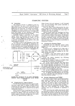
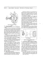
Страница 33: ...w tension circuit starting at the battery and working right through to the ignition coils stage by stage in the following manner referring to the wiring diagram I First establish that the battery is earthed correctly by connecting the volt meter across the battery negative terminal and the machine frame earth No voltage reading indicates that the red earthing lead is faulty or the fuse has blown i...

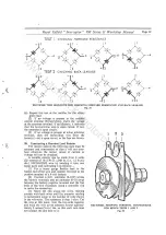
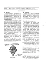
Страница 34: ... coils and test them by the method described below 82 Bench Testing an Ignition Coil Connect the ignition coil into the circuit shown in Fig 25 and set the adjustable gap to 9 mm for the MAl2 Type and 8 mm for the 17Ml2 Type With the contact breaker running at 600 r p m for a single lobe cam and the coil in good condition not more than 5 missing should occur at the spark gap over a period of 15 se...

Страница 35: ...s the choice of running with normal battery operation or running without battery if desired e g competing in trials or other competitive events and for emergency operation in case of battery failure Machines can readily be started without the battery and run as normal with full use of standard lighting When stationary however parking lights will not work unless the battery is connected The capacit...

Страница 36: ...o stand for at least 5 minutes 3 Then connect the voltmeter leads to the capacitor and note the instantaneous reading This hould not be less than 8 0 volts for a service able unit If a voltmeter is not available a rough check can b made by following the procedures in I and 2 and using a single strand of copper wire instead of the voltmeter to short circuit the capacitor terminals A good spark will...

Страница 37: ... in parallel with the two alter nator leads The minimum reading on the volt meter should be 9 volts A suitable I ohm load resistor can be made from a piece of nichrome wire as shown in Sub section 98 From the results obtained the following deductions can be made I If the reading is equal to or higher than quoted then the alternator is satisfactory TO IGN COILS ON J_ 2 A low reading indicates that ...

Страница 38: ...ly greater than that quoted then the rectifier elements in the forward direction are satisfactory I OHM R SISTOfl 1 er I 1 Cl I 6 I I Q I 0 X 0 C Q c 2 If the reading is excessively higher than the __________________________J figures given then check the rectifier earthing bolt connection If the connection is good then a re placement rectifier should be fitted 3 If the reading is lower than the fi...

Страница 39: ...d so that it will not over heat otherwise the correct values of current or voltage will not be obtained A suitable resistor can be made from 4 yards 3l metres of 18 S W G 048 in i e 1 2 m m dia NICHROME wire by bending it into two equal parts and calibrating it as follows 1 Fix a heavy gauge flexible lead to the folded end of the wire and connect this lead to the positive terminal of a 6 volt batt...

Страница 40: ...inium heat sink Providing the Diode and the heat sink are kept clean and provided with an adequate airflow to ensure maximum efficiency and pro vided a firm flat metal to metal contact is main tained between the base of the Diode and the surface of the heat sink to ensure adequate heat flow no maintenance will be necessary 101 Test Procedure Procedure for testing on the Machine The test procedure ...

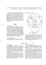
Страница 41: ...in the internal moving parts of the horn To adjust turn this crew anticlockwise until the horn just fails to sound and then turn it back clock wise about one quarter to half a turn LAMP UNITS 105 Description The headlamp is of sealed beam unit type and access is gained to the bulb and bulb holder by withdrawing the rim and beam unit assembly To do so slacken the screw at the top of the headlamp an...

Страница 42: ...itting is the reversal of the above instruction but referen e should be made to the wiring diagram Finally set the headlamp main beam as explained previously Do not tighten the headlamp pivot bolts over the torque setting of 10 lb ft 1 4 kg M 108 General Access to the bulbs in the tail and stop lamp unit is achieved by unscrewing the two slotted screws which secure the lens The bulb is of the doub...

Страница 43: ...l contact The switch body can be released from the switch panel by removing the large retaining nut and pushing the switch out The battery leads should be removed before attempting to remove the switch to avoid a short circuit The lock is retained in the body of the switch by a sprii1g loaded plunger This can be depressed with ii pointed instrument through a small hole in the side of the switch bo...

Страница 44: ...ITE Y YELLOW D DARK L LI GHT M M EDIUM AMMETER 12 VOLT BATTERY NW _ t I O O NU O NU Cl NU I0 R 3 5 7 N rHORN u NB MAIN BEAM OWARNING LIGHT U _ _ R DIP BEAM R HORN PUSH 0 RR fir _glv R9 PILOT LIGHT I 11 I TACHOMETER LIGHT l __ N G NG oXf III F I I CAPACITORS 11 i I NG SPEED LIGHT 111 IH li D4 BY I BY IH t IJH I OIL R R R NG MOULDED Iii LAMP CONNECTOR STOPLIGHTSWITCH N r N O o L_J 0 t III 2MC CAPACI...

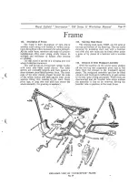
Страница 45: ...nds of the rubber bushes and bear against steel thrust washers fitting into recesses in the main frame pivot lugs A long steel bolt and nuts secure the whole assembly No greasing is necessary 113 Steering Head Races The steering head races 34085 are the same at the top and bottom of the head lug They are easily removed by knocking them out with a hammer and drift and new races can be fitted either...

Страница 46: ...hus raising the rear of the machine and preventing bottoming on the bump stop under heavy loads The lowest position is suitable for normal solo work the middle position is for use with a pillion passenger and the top position is suitable for sidecar work The part number for the spring for these dampers is 64539963 colour code red orange rating 132 lb Jin When replacing a spring the use of a compre...

Страница 47: ...bearings are well packed they will last for several years or many thousands of miles Recommended greases are Shell Retinax A Castrolease LM fsso Multipurpose Grease H Marfak Multipurpose 2 Mobilgrease MP or Energrease L2 Front Forks 121 Lubrication Use one of the grades of oil S A E 20 as shown in the table of lubricants The normal oil content is 6J fluid ozs 170 4 cc Attention is only necessary a...

Страница 48: ...n tube bush 3 Main tube bottom bush 4 Main tube bottom bush circlip 5 Fork end left hand 6 Fork end right hand 7 Fork end d ain plug 8 Washer for plug 9 Oil damper tube 10 Oil damper rod 11 Oil damper tube bolt 12 Washer for bolt 13 Washer for tube 14 Nut for rod top 15 Nut for rod bottom 16 Damper tube cap 17 Piston locating peg 18 Oil damper valve cup 19 Oil damper valve cup slotted ring 20 Main...

Страница 49: ... there is nothing complicated in the fork assembly and if the reverse sequence is used no difficulty should occur with the following pre cautions The fork tube where the oil seal operates must have a smooth finish and free from blemish The oil seal is fitted from the top of the tube with the visible spring facing downwards against the flange for the bush The damper tube cap also the damper tube fi...

Страница 50: ... washer then the large steel washer With a suitable punch peen the hub material where it joins the washer in three equidistant positions to retain the washer 133 Brake Adjustment Clearance between the brake shoes and drum can be reduced by unscrewing the adjusters on the cable and handlebar lever Continual adjustment causes the expander lever to occupy a position with lost leverage To restore leve...

Страница 51: ...k To counter balance use thin strips of lead twisted round the spoke Special weights for this purpose are supplied by the tyre makers When the wheel is in perfect balance secure the strips of lead with insulating tape which should be painted with jointing com pound The effect of a balanced wheel has to be tried to be appreciated if continued high speeds are permissible Rear Hub 137 Description Thi...

Страница 52: ...meter driw gearbox are engaged with the slots in the end of the hub barrel Make sure also that the speedometer drive gearbox is correctly positioned so that there is no sudden bend in the driving cable When replacing the connecting link in the dri ing chain make sure that the closed end of the spring link points in the direction of travel of the chain Replace the chain adjuster cams in their origi...

Страница 53: ... described above To remove the bearing from the sprocket brake drum first remove the brake cover plate complete with brake shoe assembly then remove the distance collar and unscrew the bearing re taining ring with a peg spanner Now screw the loose section of the spindle into the fixed section and drive out the bearing by hitting the hexagon headed end of the loose section of the spindle To remove ...

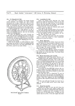
Страница 54: ...l lithium soap greases and should not be mixed with lime aluminium or soda soap greases Make sure that the inside of the brake drum is free from oil grease dust or damp Replace the felt washers distance collars and brake cover plate and securely tighten the spindle nuts 150 Wheel Rim The wheel rim is WM3 l 8 in plunged and pierced with forty holes for spoke nipples The spoke holes are symmetrical ...

Страница 55: ...the pressure by I lb per sq in for every I4 lb increase in weight above 154 lb If additional load is carried in the form of a pillion passenger or luggage the actual load bearing upon the tyre should be determined and the pressure increased in accordance with the following table 155 Lubrication Grease the bearings by packing them with grease after removal of the brake cover plate and speedometer d...

Страница 56: ...age 56 Royal Enfield Interceptor 750 Series II Workshop lvfanual Special Tools W 49994 CAMSHAFT SEAL ASSEMBLY THIMBLE T 2055 19 ASSEMBLY GAUGE IN USE TO CENTRALISE ROTOR E 5425 PUMP DISC LAPPING TOOL X 6 f 1111 11 y W 49926 GEARBOX COLLAR SPLINED EXTRACTOR ...

Страница 57: ...m Royal Enfield Interceptor 750 Series If Workshop Manual T 2053 1NLET VALVE SEAT ARBOR T 2054 ll LET VALVE SEAT CUTTER 1tl iC Y A J B W 49909 CLUTCH HUB EXTRACTOR W 49925 TAPPET GCIDE EXTRACTOR _ _ _ I C m 2 0 1 o _ b W 49919 CLUTCH HOLDING TOOL Page 57 ...

Страница 58: ... o m Page 58 Royal Difield Interceptor 750 Series II Workshop Manual 71 i_ ___ ___ _ 1 r 1 4 lJ1 y _ y W 49907 CAMSHAFT SPROCKET EXTRACTOR W 49910 CRANKSHAFT EXTRACTOR W 50011 DRIFT FOR ASSEMBLY OF TIMING COVER SEALS W 49908 ENGI E SPROCKET NUT SPA ER ...

Страница 59: ...w w w h i t c h c o c k s m o t o r c y c l e s c o m Royal field Interceptor 750 Series ff Workshop Manual Page 59 NOTES ...

Страница 60: ... h c o c k s m o t o r c y c l e s c o m Page 60 Royal Enfield fmerceptor 750 Series If Workshop Manual NOTES Pub Ii sh d by G R E G PU 8 LICIT Y St our b rid I e Printed in Englund by GIBBONS of Wo 1 1 rhu111p t on ...

Отзывы: