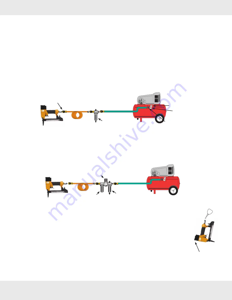
The following diagram shows a simple compressed air set-up.
Connect a filter to air compressor through a straight air hose. Connect the stapler to the filter with a coiled
air hose. Straight air hose is ideal for long distances. A coiled air hose gives the user more freedom while using
stapler and is safer when the tool is not in use. Use quick couplers for easy connecting/disconnecting. Make sure
all the air hoses are rated with working pressure exceeding 200 psi. The air compressor usually has two air pres-
sure gauges: One indicates the tank pressure; the other output air pressure. Use the regulator knob to adjust the
output air pressure starting at 70 psi and increase if necessary.
The filter removes moisture and debris from compressed air and protects the interior parts of the stapler
from unnecessary wear
(Fig 3)
. Without filter, the stapler may shoot rusty water. The rusty water is from the tank.
Empty water from the tank regularly by following the air compressor manufacturer's instruction.
2
OPERATION INSTRUCTIONS:
1) Set up Compressed Air:
An in-line lubricator and regulator can also be added as shown in
Fig. 4
.
The in-line lubricator is a convenient way to lubricate the tool. If an in-line lubricator is installed, do not lu-
bricate the stapler manually. Check the lubricator's oil level frequently. The air pressure regulator regulates output
air pressure. It is better than the one on the air compressor since it is closer to the tool.
A separate regulator is especially useful when there are several tools connected to the same air compres-
sor, or when the air hose spans a long distance. Always install an air regulator as close to the tool as possible.
2) Lubricate The Stapler:
Note: Stapler requires lubrication before first time use, or after a long period of no use.
1. Disconnect the stapler from air supply.
2. Turn the stapler so that air inlet faces up. Squeeze three drops of pneumatic oil into the air inlet
(Fig. 5)
.
3. Wipe off any excess oil at the exhaust cap.
4. Connect the stapler to the compressed air. Without loading staples, press trigger several
times to shoot empty, wipe off any excess oil.
Note:
Use pneumatic oil only. If the stapler is not connected to an in-line lubricator, it needs to be
lubricated regularly. Add one or two drops of oil at the start of each work day.
If tool is connected to an in-line lubricator, manual lubrication is not needed.
Warning:
If the stapler is not sufficiently oiled, the piston blade may stick and misfire. Fail to oil the
stapler may damage the tool.
Warning:
Over oiling can damage O-rings and cause air leak.
OIL
OIL
OIL
Exhaust Cap
Fig. 5
Fig. 4
Fig. 3
Regulator (adjust air pressure here)
Filter
In-line Lubricator
(optional)
Filter
Tank
Air Compressor
Tank Pressure Indicator
Output Pressue Indicator
Regulator Knob
(adjust air pressure here)
Straight Air Hose
Coiled Air Hose
Quick Coupler


