Rowan Elettronica 119/92 Скачать руководство пользователя страница 14

ROWAN ELETTRONICA  S.R.L. - Via Ugo Foscolo, 20 - 36030 CALDOGNO (VICENZA)  ITALY

14

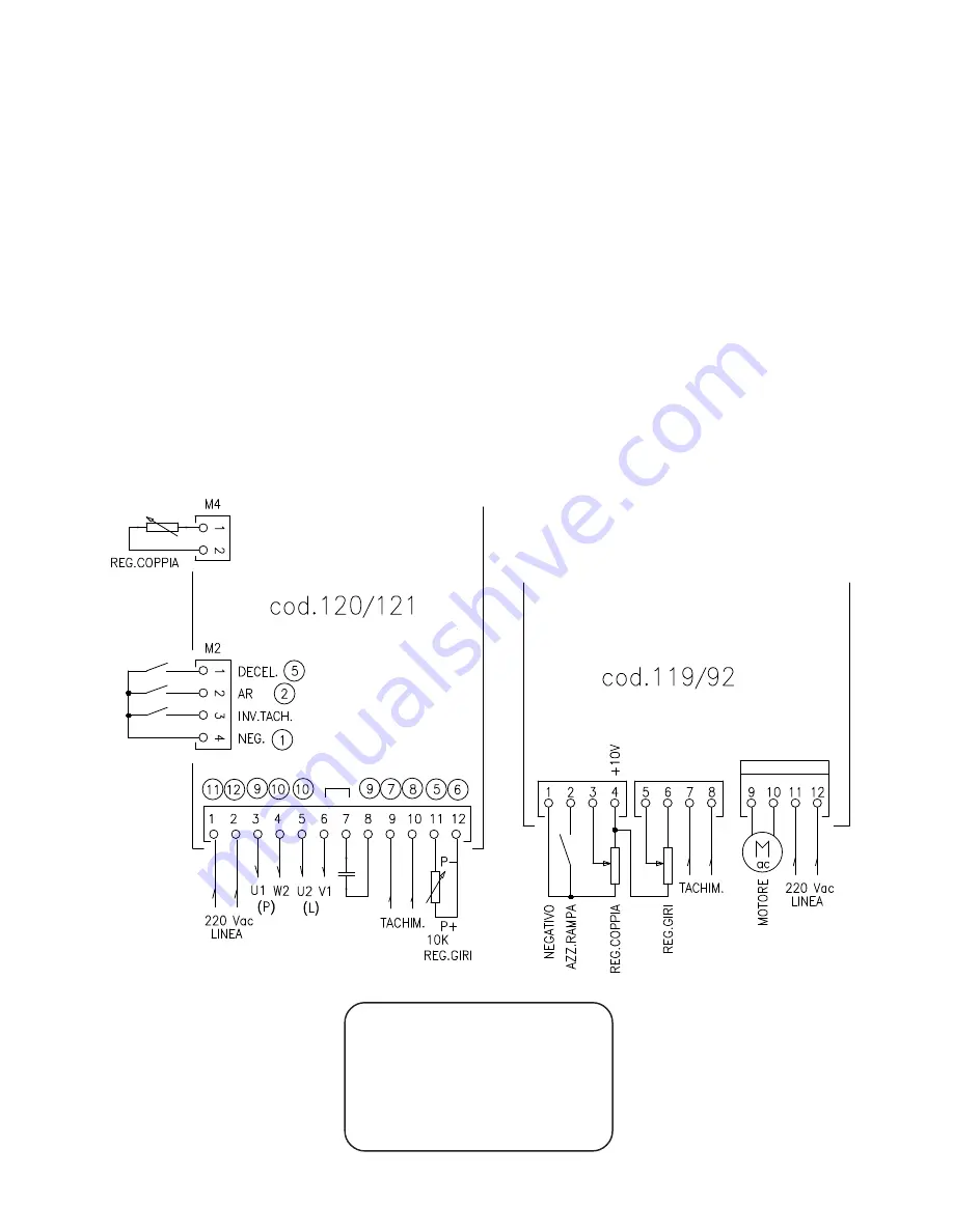
For the power connections proceed as follows:
the wires that were connected to the terminals 1 and 2 are to be shifted to terminals 11 and 12 of C119/92, whereas
the wires connected to terminals 3 4 5 6 7 8 related to the capacitor and power and launching windings are to be
reconnected together as shown in the schematic.
For the control connections proceed as follows:
the tachometer wires that were connected to terminals 9 and 10 are to be connected to terminals 7 and 8 of  C119/92,
whereas the potentiometer wires as follows: P-(OV), connected to terminal 11, must be shifted to terminal  6,
whereas P+, connected to terminal 12, must be shifted to terminal 5 of C119/92.
For control wires connected to lateral terminal strip M2 of board C120/121 proceed as follows:
shift the wire connected to terminal NEG to terminal 1 of C119/92;
shift the wire connected to terminal  AR to terminal 2 of C119/92;
exclude the wire connected to terminal INV. TACH. since it is unnecessary for C119/92;
connect wire connected to terminal DECEL to terminal 5 of C119/92.
Close microswitch S1 (for other microswitches refer to the paragraph describing the microswitches).
If a potentiometer is connected to terminal board M4 for torque limitation, you should reconnect it to terminals
1 3 4 of  code 119/92  with 3 wires as illustrated in the schematic diagram; in this case close microswitch S2.
The circled numbers in the schematic refer to the terminals on C119/92.

Reg. Coppia = Torque Regulation

Reg. Giri =  Speed Regulation

Tachim.= Tachometer Generator

Linea = Mains Line

Negativo = Negative

Azz. Rampa = Ramp to zero setting

Inv. Tach. = Tachometer Inversion

Decel = Deceleration

Replacing drive C120/121 with drive C119/92

Содержание 119/92

Страница 1: ...NUAL CODE119 92 REV 7 Date 15 10 18 EMC CONFORMITY FORASYNCHRONOUS ROWAN SINGLE PHASE MOTORS with TACHOMETER Motori azionamenti accessorieserviziperl automazione Via Ugo foscolo 20 CALDOGNO VICENZA IT...

Страница 2: ...any inaccuracies contained in this manual due to printing and or transcription errors ROWAN ELETTRONICA s r l reserves the right to make any variations that it considers necessary for better function...

Страница 3: ...ally through potentiometer or 0 10Vdc signal Input for pure contact or NPN open collector transistor for static run stop command 12Vdc 2mA Internal regulations through trimmer for acceleration deceler...

Страница 4: ...ed system extremely silent Absence of typical PWM whistle and uniform from zero to the maximum motor rounds The application of controlled diodes on the power part gives reliability against extravoltag...

Страница 5: ...3kohm load regulation external potentiometers 1 5 speed regulation 0 10VDC signal input 0VDC zero turns 10VDC max speed 1 extreme 3 cursor torque limitation external potentiometer connection 4 extreme...

Страница 6: ...terorfrom0 10VDCsignalconnectedtoterminal3 closed activates board internal torque limitation from trimmer P1 S2 open cuts out torque limitation closed activatestorquelimitation S3 open in case of 3 wi...

Страница 7: ...l it can be used for analog revolution counters display counters or other servomechanisms provided the overall loading being not lower than 5Kohm maxtachometercurrent 5mA Itisalwaysnecessary toavoidin...

Страница 8: ...te it means that tachometer dynamo voltage is not reaching terminals 7 and 8 when this happens check the connections again Check attainment of maximum speed and if necessary fine adjust the maximum va...

Страница 9: ...oswitch S1 and limit torque by regulating trimmer P1 Speed torque control from analog signal 0 10VDC In code 119 92 speed and torque regulations in addition to the conventional manual potentiometer ca...

Страница 10: ...sets the ramp and switches off RUN led L2 If motor run stop were necessary with acceleration and deceleration ramps without immediately removing voltage from the motor in its stopping phase perform th...

Страница 11: ...ve the screws attaching the brake to the hub 4 disconnect the brake cable from the terminal block 5 slide the brake off the hub At this stage the calibration can be made by adjusting the 3 bolts until...

Страница 12: ...of motor windings with relative terminal board covering 9 FEET for B3 or B3 B5 versions 10 THERMICSENSORINSIDEWINDINGS 11 COMPENSATORRING 12 REAR RING for rear bearing housing 13 SERVICE TERMINAL BOA...

Страница 13: ...r but according to an exponential curvewhichpresentsstrongvariationsatslowspeedandsmallvariationsathighspeed Ifonewishestoavoidthis behaviour and obtain a variation directly proportional to potentiome...

Страница 14: ...of board C120 121 proceed as follows shift the wire connected to terminal NEG to terminal 1 of C119 92 shift the wire connected to terminal AR to terminal 2 of C119 92 exclude the wire connected to t...

Страница 15: ...ROWAN ELETTRONICA S R L Via Ugo Foscolo 20 36030 CALDOGNO VICENZA ITALY BLOCK DIAGRAM...

Страница 16: ...Foscolo 20 36030 CALDOGNO VICENZA ITALY EMC CONFORMITY Motori azionamenti accessorieserviziperl automazione Via Ugo foscolo 20 CALDOGNO VICENZA ITALY Tel 0039 444 905566 Fax 0039 444 905593 E mail inf...

Отзывы: