Adjustable Lock Jig
5.
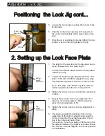
Loosen the two screws securing the lock jig to the
fixing plates.
6.
Align the centre line engraving on the jig (CL) to
the centre line markings which were made on the
door.
7.
Once the jig is positioned correctly, tighten the two
screws to secure the fixing plates to the jig.
1.
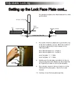
The length of the aperture for the face plate has to
be set. Measure the face plate length.
For this exercise lets assume that the face plate is
100mm (4”) long.
2.
Loosen the bottom length adjustment screw, and
slide it to 50 (half of 100mm). Note: The top edge
of the bottom adjustment has to be in line with 50.
If your face plate was 150mm long then slide the
bottom adjustment so that it is in line with 75.
3.
Tighten the screw to secure the bottom adjustment
in place.
4.
Repeat this process for the top adjustment. For
instance, if your face plate is 100mm long then
move the top adjustment to 50.
5.
Tighten the screw to secure the top adjustment in
place.
6.
The aperture length (the distance from the top
adjustment to the bottom adjustment) should be
3.3mm longer than the actual face plate. This is
due to the cutter and bush offset.
For instance, if your face plate is 100mm long then
the distance between the adjustment plates should
be 103.3mm. See the diagram on the next page for
an explanation.
Positioning the Lock Jig cont...
Positioning the Lock Jig cont...
Fixing Pate
Screws
Centre Line
Engraving
Bottom
Length
Adjustment
2. Setting up the Lock Face Plate
2. Setting up the Lock Face Plate
Top
Length
Adjustment


