-11-
Characterization
– This option provides for a 2 to 11 point
calibration of the unit in order to characterize its output. This
calibration is performed under the VALVE POS menu via the
following steps:
1. Update the MAX POSITION parameter to reflect the
value of the maximum output position of the actuator.
(ex. 100 %)
2. Select the CAL POINT 1 parameter. Use the
↑
/
↓
knob
to run the actuator to the desired ZERO position. Select
E
nter to save the current physical position of actuator as
its ZERO point.
3. Continue to the CAL PT 1 VAL parameter and select it for
update. This is the numeric value that is to be associated
with the ZERO point (ex 0 %). Update and select
E
nter to
save this value
4. Continue to the CAL POINT 2 parameter. Use the
↑
/
↓
knob to run the actuator to the desired position. Select
E
nter to save the current physical position of actuator as
the second calibration point.
5. Continue to the CAL PT 2 VAL parameter and select it for
update. This is the numeric value that is associated with
the second calibration point (ex 10 %).
6. Continue to the CAL POINT 3 parameter. Use the
↑
/
↓
knob to run the actuator to the desired position. Select
E
nter to save the current physical position of actuator as
the third calibration point.
7. Continue to the CAL PT 3 VAL parameter and select it for
update. This is the numeric value that is associated with
the third calibration point (ex 20 %).
8. Calibration points (up to 11) will be automatically
available until the CAL PT X VAL parameter is set equal to
the MAX POSITION parameter value set in step 1. When
this occurs, calibration is considered complete; no
additional calibration points are provided.
ACTUATOR SETUP
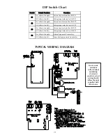
5) Transmitter
The unit may be configured to use either an internally
powered transmitter (S4 slid to the right, in line with the
painted line) or as externally loop powered (S4 slid to the
left, not in line with the painted line) The transmitter is
factory calibrated. User calibration is not required.
6) Loss of Command Action
The unit may be configured to perform one of four actions
when a loss of the command input signal occurs while
running under the automatic operation of the Open Loop
control mode:
LOCK – Locks the unit in place at its current position
DRIVE to ZERO - The unit will drive to the ZERO position
set in calibration
DRIVE to SPAN - The unit will drive to the SPAN position set
in calibration
DRIVE to POS - The unit will drive to a user position
specified by the CMD LOS POS parameter
7) Loss of Process Variable Input Action
The unit may be configured to perform one of four actions
when a loss of the process variable input signal occurs under
the automatic operation of the Closed Loop control mode:
LOCK - Lock the unit in place at its current position
DRIVE to ZERO - The unit will drive to the ZERO position
set in calibration
DRIVE to SPAN - The unit will drive to the SPAN position set
in calibration
DRIVE to POS - The unit will drive to a user position
specified by the PV LOS POS parameter

