1400268-9S_D14.754.19.03_2019-07-20 QuattroPowerSupportKid Eng
Page
5
from
12
3. Operation / assembly
3.1 Mounting
(see page 8)
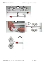
(Fig. 1) Push in the snap-lock pins from the bar connector (B) and insert into the short bar (C) until the snap-lock pin
engages in the hole. (Fig. 2 arrow) Then insert the long bar (part D) into the bar connector (B). Insert the two bars (C
and D) into the suction head connectors (A) (fig. 3).
Test the secure hold of the snap-lock pins by trying to pull the components apart!
The handle must not be used if not all snap-lock pins on both sides are securely locked.
3.2 Attaching / suction:
(see pages 10 and 11)
1. Examine the vacuum suction pads and the surface they are to be attached to.
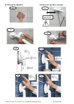
2. Clean the surface thoroughly (fig. 11) so that it is
clean
(e.g. from etched lime sludge) and
grease-free
.
Likewise, the surface of the suction disc must be clean.
3.
Firmly press the mobile grab handles onto the surface where they should be sucked on
(fig. 13).
a. The
tilting vacuum levers
must be
loose
at this point.
b. It should be noted that both rubber discs are always fully positioned on tiles or other surfaces so that
there is no joint under the rubber disc and the discs are positioned at least 10 mm above the lower
edge of the joint.
4. While
pressing the bar against the surface to be adhered to and at the same time pressing on the
rocker
, turn over the 1
st
rocker and then the 2
nd
rocker (figs. 2, 3, 4, 5, 17.18).
5. Attach the lower suction cups (fig. 14) by turning the suction heads (see arrow) so that they are flat on the wall
(turn with some force using the built-in safety brakes)
.
6. The vacuum safety indicators continuously monitor the current vacuum state.
After the rocker is pressed and turned, the red-coloured safety tab must be
completely recessed flush with
the surface
in the rocker (page 11, figs. 19 and 21)! In the course of time when the vacuum decreases, the
safety rockers will extend.
•
If a red side edge of the safety tabs (figs. 20 and 22) has become visible, the grab bar must not be
used under any circumstances and
must be reattached
immediately!
•
The clearer a red side edge of the tabs
(figs. 14 and 22)
can be seen, the lower is the actual
adhesive strength!
7. Check the vacuum safety indicator prior to any use. This can be felt by visually impaired or blind people. If the
vacuum safety indicator is not retracted (as just described), reattach the bar. If the indicator tabs are still
raised after the rocker has been turned and also are still sticking out after the tabs have been pressed, the
grab bar must be reattached (cf. malfunctions on page 7).
If retraction of the indicator tabs cannot be achieved, do not use the bar under any circumstances!
3.3 Releasing:
1. Put a finger under the vacuum tilting lever in order to raise it; at the same time set your thumb on the
structured recess of the vacuum tilting lever to prevent a recoil effect.
Caution! With wrong operation there
exists danger of squeezing.
2. Wait a little while! The rubber pads will relax after approx. 30
–60 seconds and return to their original shape,
and then the suction device can be removed from the wall. Now the suction cup can be removed from the
wall. Should the rubber pads keep adhering longer, you can additionally raise the pads at one side (between
wall and rubber disc) with a finger so that air can penetrate underneath.
3.
Do not try to loosen the rubber pads with sharp edged items or tools; you would damage them.
4. When not in use, store the mobile grab handle with the rubber pads relaxed (i.e., with vacuum tilting levers
disengaged), flat and plane. Protect your mobile grab handle (e.g. in the box) from UV rays.
3.4 Disassembling
(see page 8 and 9)
Press in the quick-release locking device of the rods with the enclosed press-in aid
(without
red part) and pull the rod
out of the held suction head connector (figs. 5 and 6).
Press in the quick-release lock (fig. 7 and 8 see arrows) with the enclosed press-in aid
(with
red part) and pull the
rods out of the held rod connector (fig. 8).
Disassembly of the rod connectors and suction parts:
Push in the quick lock (fig. 9) of the suction head connector using the push-in aid supplied
(without
red part) and pull
the suction housing out of the held suction head connector (fig. 10).

