


Installation
20
5.3
Assembly at the installation site
5.3.1
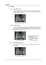
Setting up
NOTICE
Incorrect setup or assembly
Incorrect setup or assembly of the machine can lead to equipment damage and
increased wear.
•
Follow the instructions for setup and assembly.
Mechanical assembly work
X
Measure the underframe of the machine and transfer the measurements to
the installation site.
X
Measure the height differences at the designated corners.
X
Compensate for the differences at the corners with base plates laid under-
neath.
X
Erect the machine at the installation site.
X
Check the machine with a water level and employ additional base plates if
necessary.
X
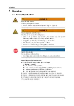
Dowel the machine as follows (Fig. 5-2, page 21):
X
Drill holes (borehole diameter: 16 mm; borehole depth: min. 110 mm).
X
Clean boreholes.
X
Insert dowels.
X
Insert washers and nuts.
X
Tighten nuts (torque 100 Nm).
X
Lay the control and supply lines.
The mechanical installation work is complete.
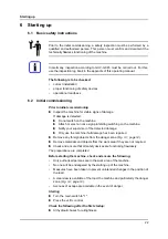
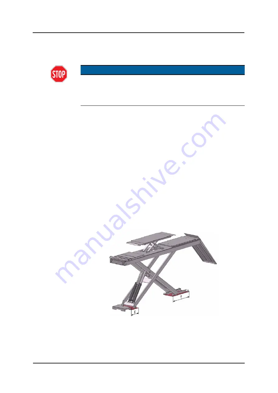
Fig. 5-1 Fixed bearing area (x) and castor area (y) of the underframe
Содержание ML40
Страница 2: ......
Страница 43: ...Appendix 41 11 Appendix...
Страница 44: ...Appendix 42 Mechanical components...
Страница 46: ...Appendix 44 Mechanical components...
Страница 91: ......


