background image

14 • Hardware Overview

TSI-100 User Guide (v5.0)

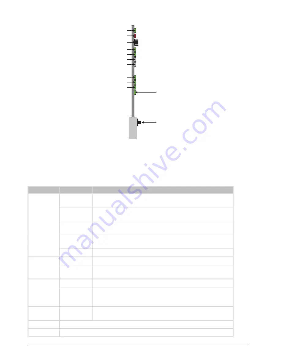
Figure 2.2  TSI-100 Card-edge Controls

Status and Selection LEDs on the TSI-100

The front-edge of the TSI-100 has LED indicators for communication activity. Basic LED displays and descriptions 
are provided in 

Table 2.1

.

Table 2.1  LEDs on the TSI-100

LED

Color

Display and Description

POWER 
(DS1)

Green

When lit green, this LED indicates that the card is running with a valid 
input.

Flashing Green When flashing green, this LED indicates that the bootloader is waiting for 

a software upload.

Yellow

When lit yellow, this LED indicates there is a warning for a signal or a 
configuration error is occurring.

Red

When lit red, this LED indicates that the card is not operational. This will 
occur if, for example, there is not video input.

Off

When off, this LED indicates that there is no power.

BYPASS 
(DS2)

Red

When lit red, this LED indicates the card is in bypass mode.

Off

When off, this LED indicates the card is in the video path and is capable 
of inserting data.

ASI IN (DS3)

Green

When lit green, this LED indicates the ASI input is present and valid.

Off

When not lit, this LED indicates that no valid input is present. This 
typically means that the input cable is disconnected or the signal is not 
ASI (e.g. SDI or HD-SDI).

ASI OUT 
(DS4)

Green

When lit green, this LED indicates the ASI output serializer is locked to a 
valid input.

DS5

This LED is not implemented.

DS6

This LED is not implemented.

POWER LED (DS1)

BYPASS LED (DS2)

Bypass Switch (SW1)

 ASI IN LED (DS3)

 ASI OUT LED (DS4)

DS5 LED

 DS6 LED

UNSUPPORTED REAR MODULE LED (DS7)

BYPASS LED (DS8)

NO VIDEO LED (DS9)

UNKNOWN REAR MODULE LED (DS10)

Reset Button (SW3)

Содержание openGear TSI-100

Страница 1: ...TSI 100 User Guide...

Страница 2: ...eople that make things happen At Ross our employees are a special group Our employees truly care about doing a great job and delivering a high quality customer experience every day This code of ethics...

Страница 3: ...nual is furnished for informational use only It is subject to change without notice and should not be construed as commitment by Ross Video Limited Ross Video Limited assumes no responsibility or liab...

Страница 4: ...intended for use in areas outside home International This equipment has been tested under the requirements of CISPR 22 2008 or CISPR 32 2015 and found to comply with the limits for a Class A Digital...

Страница 5: ...vironmentally friendly and health conscious manner The crossed out wheeled bin symbol invites you to use these systems If you need more information on the collection reuse and recycling systems please...

Страница 6: ......

Страница 7: ...tures 13 Status and Selection LEDs on the TSI 100 14 Cabling for the TSI 100 15 MDL R10 Rear Module 15 MDL R20 Rear Module 15 Connections Overview 16 ASI In BNC 1 16 ASI Out BNC 3 16 GPIOs 16 Physical...

Страница 8: ...ii Contents TSI 100 User Guide v5 0 Technical Specifications 25 Service Information 27 Troubleshooting Checklist 27 Warranty and Repair Policy 27 In Case of Problems 27 Glossary 29...

Страница 9: ...mended to consult the following Ross documentation before installing and configuring your TSI 100 DashBoard User Guide Ross Part Number 8351DR 004 MFC OG3 N and MFC 8322 S User Guide Ross Part Number...

Страница 10: ...s you have access to technical expertise around the clock After sales service and technical support is provided directly by Ross Video personnel During business hours Eastern Time technical support pe...

Страница 11: ...als a remote device or alarm when an incorrect transport stream or no transport stream is present Simple setup enter the TSID of the transport stream Two GPIOs provide both normally open and normally...

Страница 12: ...and Control The Network Controller Card in the openGear frame provides optional support for remote monitoring of your frame and using the Simple Network Management Protocol SNMP which is compatible wi...

Страница 13: ...button is used to control the relay When the push button is in the IN position the TSI 100 is in the video signal path It is recommended to set SW1 in the IN position at all times Pressing it once mo...

Страница 14: ...This will occur if for example there is not video input Off When off this LED indicates that there is no power BYPASS DS2 Red When lit red this LED indicates the card is in bypass mode Off When off t...

Страница 15: ...r on screen display and relay isolated GPIO outputs Figure 2 3 Figure 2 3 Cabling for the MDL R10 and MDL R20 Rear Modules Unsupported Rear Module DS7 Green When lit green this LED indicates correct o...

Страница 16: ...input signal is internally terminated in 75ohms when the TSI 100 is installed ASI Out BNC 3 BNC 3 carries a reclocked copy of the ASI signal applied to BNC 1 GPIOs Two blocks of relay isolated GPIO ou...

Страница 17: ...ard client on a computer connected to the LAN The DashBoard Control System software and user manual is available from the Ross Video website 2 Install the required Full Rear Module in the frame as des...

Страница 18: ...will be low and GPIO2 will be high when the transport stream is present and the TSID is correct Installing the TSI 100 This section outlines how to install a rear module and card in an openGear frame...

Страница 19: ...age 18 2 Hold the TSI 100 by the edges and carefully align the card edges with the slots in the frame 3 Fully insert the card into the frame until the rear connection plus is properly seated in the Re...

Страница 20: ...20 Physical Installation TSI 100 User Guide v5 0...

Страница 21: ...tory Defaults Reset button clears all configuration settings and restores the settings to as they were shipped from the factory TSID Setup This section outlines how to configure the card for matching...

Страница 22: ...t signal is connected or not to the rear module Rear Module This field reports when an unsupported rear module is installed with the TSI 100 TSID This field reports the four digit hex number Transport...

Страница 23: ...een instructions 7 Click Finish to start the upgrade 8 Monitor the upgrade A Upload Status dialog enables you to monitor the upgrade process The card reboots automatically once the file is uploaded Th...

Страница 24: ...24 Upgrading the Software TSI 100 User Guide v5 0...

Страница 25: ...Inputs Number of Inputs 1 Input Signal Standard Accommodated DVB ASI EN 50083 9 Impedance 75ohm terminating in Active mode Equalization 100 m of Belden 1694A cable Return Loss 15dB to 270 MHz Transpo...

Страница 26: ...26 Technical Specifications TSI 100 User Guide v5 0...

Страница 27: ...lid signal 7 Unit Exchange Exchanging a suspect unit with a unit that is known to be working correctly is an efficient method for localizing problems to individual units Warranty and Repair Policy The...

Страница 28: ...temporary replacement frame will be made available at a nominal charge Any shipping costs incurred will be the responsibility of you the customer All products shipped to you from Ross Video Limited wi...

Страница 29: ...data essence not metadata For convenience this manual uses the term metadata to refer to all VANC data types MIB management information base Network Controller Card the MFC OG3 N and any available opt...

Страница 30: ...30 Glossary TSI 100 User Guide v5 0...

Отзывы: