


F3.18
© 2016,
ROSS
CONTROLS
®
.
All Rights Reserved.
IMPORTANT NOTE:
Please read carefully and thoroughly all of the
CAUTIONS, WARNINGS
on the inside back cover.
Online Version
Rev. 11/14/16
Mounting Accessories
Digital Pressure Transducer
Precision digital pressure transducer with 5 pin female connection
• Two PNP digital outputs which may be set individually, 4-20 mA analog output
• Three operation modes: Easy, Window and Hysteresis
• Selectable response times to eliminate output chattering
• Powered by 12-24 vots DC
• 6 pressure unit conversions
• Lockable keypad
• Fast zero reset
BROWN
Input
Power +
GREY
Power Input
WHITE
Digital
Output Signal
BLUE
Digital
Output 2 Signal
BLACK
Analog
Output Signal
1
2
3
4
5
Wiring Kits
Mounting Bracket Kit includes bracket and bolts
to mount to the valve end plate.
At least two mounting brackets should be used.
This can consist of two clamp mounting brackets or one clamp mounting bracket and one mounting bracket Kit Number 2433H77.
0.75 (19.1)
0.375
(9.5)
3.2 (81.3)
0.34
(81.3)
0.25
(6.4)
0.44
(11.1)
3.0 (76.2)
3.875 (98.4)
8X
R 0.13
3.0
(76.2)
3.0 (76.2)
R 0.063
90°
1.82
(46.2)
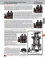
Control Reliable Modular Double Valves
with Integrated Soft Start
M DM
2®
Series C
Accessories & Options
Model Number
2447H77
Kit Number
Length
2431H77
Wiring Kit - 5 meters (16.4 feet). Includes two cords, and the cord grips.
2432H77
Wiring Kit with Transducer - 5 meters (16.4 feet). Includes three cords, and the cord grips.
Kit Number
2433H77
F
An extra port block can be placed between modules to provide
two auxiliary 1/4 NPTF ports. Its mounting position can be
rotated to obtain the most convenient operating orientation. If
only one auxiliary port is to be used, the unused port must be
closed with a pipe plug. (The inlet and outlet are not threaded.)
Specially designed clamps provide a quick and easy assembly
or disassembly of MD3
TM
modules. Two allen-head bolts quickly
tighten or loosen the clamp using a 5/32 or 4mm hex key. The
clamp contains a plate carrying two O-rings to provide positive
sealing between modules.
Order clamp by part number
R-A118-105
.
Combined clamp and bracket (below) can be ordered by part
number
R-A118-105M
.
Mounting Bracket
Part No. R-A118-103
Module Connecting Clamp
Part No. R-A118-105
Combined Clamp & Bracket
Part No. R-A118-105M
Port Size
Part Number
*
1/4
R-118-106-2
3/8
R-118-106-3
1/2
R-118-106-4
*
For BSPP threads, add a “
W
” suffix to the model number,
e.g., R-118-106-2
W
.
Port
Size
Male Part
Number
*
Port
Size
Female Part
Number
*
1/4 R-118-109-2F
1/4
R-118-100-2
3/8 R-118-109-3F
3/8
R-118-100-3
1/2 R-118-109-4F
1/2
R-118-100-4
3/4 R-118-109-6F
3/4
R-118-100-6
*
For BSPP threads, add a “
W
” suffix to the model number,
e.g., R-118-109-2F
W
.
Clamp for Module Connections
Two brackets are normally used to mount an FRL to a vertical
surface. The mounting bracket attaches to the module
connecting clamp (see above) with a single screw. Each bracket
then employs two bolts (1/4” or 6mm) to connect the assembly
to the mounting surface.
Order bracket and screw by part number
R-A118-103
.
Combined bracket and clamp (above) can be ordered by part
number
R-A118-105M
.
Mounting Brackets
Either male or female end ports can be attached to threaded inlet
and outlet lines. This allows all modules of an FRL assembly to
be removed easily and quickly without having to unthread the
end modules. The end ports are attached to the modules with
clamps (see at left). End ports can be included in an assembled
FRL or ordered separately by the following part numbers:
Male and Female End Ports
Extra Port Blocks
Mounting Bracket Kit
F3


