Rosco STSM207 Скачать руководство пользователя страница 7

12

13

Marker No.
(Pattern)

Camera Install

Height

Vehicle

Width

P1

P2

P3

P4

P5

P6

P7

2,000

2,250

2,500

2,750

3,000

3,250

3,500

2,500

2,300

2,500

-  Press [      ] button four times, and select MARKER SELECT menu. 
-  Press [           ] button, and switch marker pattern.

*  Distance marker function setting is only possible when MARKER SETUP ON is selected 

on CAM1, full screen mode. 

ON SCREEN DISTANCE MARKER SETTING

7

MARKER SETUP

ON

OFF

CAM1

In CAM1 full screen, 

press [      ] button.

Select ON/OFF with [         ] button 

and then press [      ] button.

•  The onscreen distance markers should be considered as a general reference to assist the 

driver in assessing the distances depicted on the screen. The distance markers have been 
designed based on the “CCD camera installation conditions” listed in the next section, but 
differences in vehicle design and construction may result in the actual installation condition 
or location being different from the conditions listed. In such cases, the display location 
should be set at the closest marker No. 

•  Distance markers cannot be set if non CAMOS cameras are used.

Warning

•  The markers may not indicate the exact position of the bumper, the vehicle’s width or the 

distance to the rear. Use as a reference only.

Caution

MARKER
SELECT

P1

7m

5m
3m

1m

Bumper position

(From bumper toward rear)

Vehicle width

(Unit:mm)

■  CCD camera installation conditions 

(distance marker input conditions)

1) Marker selection

CAM1

CAM2

CAM4

SCREEN SWITCH WHILE TRIGGER INPUT

8

What is <Trigger input> or <Trigger signal>? We call it when a circuit works by a signal for 
example if driver uses right/left turn signal or reverse gear, the monitor shows connected 
camera screen on driving mode.

1)  If there is trigger signal input, the connected screen (Trigger input screen) is display as full 

screen and the screen goes former one when the signal is disappear.

*  Below example is set with TRG1(Rear light)=CAM1 / TRG2(Left signal light)=CAM2 / TRG3(Right 

signal light)=CAM3 / TRG4(etc.)=CAM4.

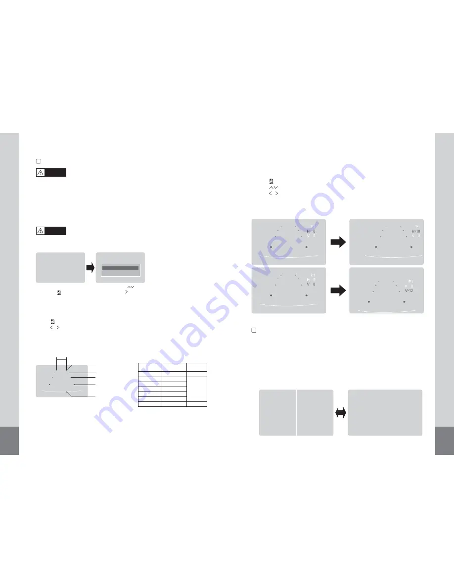
2) Marker adjustment (Adjusting the bumper position)

-  Press [      ] button five times, and select MARKER ADJUST menu.
-  Press [           ] button, select H / V. (H:  horizontal / V: vertical )
-  Press [           ] button, and switch marker pattern. 

(H = -10 ~ +10, V = -12 ~ +12, Default setting: H = 0, V = 0)

-  After 10 seconds, set up screen disappears, and set up finishes.

* If there is no button operation, set up screen disappears even during set up process.

Содержание STSM207

Страница 1: ...WATERPROOF MONITOR Thank you for purchasing this product For correct usages and application please read this instruction manual thoroughly PRINTED IN KOREA ver 1 1 Design and specifications are subje...

Страница 2: ...3 CONTENTS SAFEGUARD INSTRUCTIONS FEATURE CONTENTS FUNCTION OF EACH PART FUNCTION SETTING INSTALLATION CONNECTION SPECIFICATION 4 6 6 7 8 16 18 20 21...

Страница 3: ...k lamp head lamp and wipers operate properly When the power cable cord touches a metal case cover it with a friction tape Short circuit or disconnection of wire may cause a fire or accident Do not dis...

Страница 4: ...omatic brightness control sensor DIMMER MODE UP DOWN LEFT RIGHT MENU POWER Stand by lamp SunVisor installation hole Speaker hole Waterproof 6 7 7 WATERPROOF MONITOR 7 WATERPROOF MONITOR Water Resistan...

Страница 5: ...OR FUNCTION Press button Press button again to switch off Ifthereisnovideoinput thenthecamerawill be shown Black The screen is set 4 split from the factory SCREEN SWITCH 3 VOLUME CONTROL 2 Press butto...

Страница 6: ...IT SETUP SETTOP LEFT SETTOP RIGHT SET BOTTOM LEFT SET BOTTOM RIGHT SELECT INPUT CAM 1 CAM 2 CAM 3 CAM 4 NORMAL MIRRORVIEW SWITCH 6 1 CAM1 full screen MARKER SETUP ON OFF CAM1 Press button MIRROR SET C...

Страница 7: ...exact position of the bumper the vehicle s width or the distance to the rear Use as a reference only Caution MARKER SELECT 7m 5m 3m 1m Bumper position From bumper toward rear Vehicle width Unit mm CC...

Страница 8: ...M1 or CAM1 CAM3 could be displayed CAM1 CAM2 CAM1 button CAM1 CAM3 button CAM1 CAM4 CAM2 CAM3 CAM1 CAM2 4 In case of light on emergency blinker TRG2 TRG3 the monitor display CAM1 CAM4 as quad split sc...

Страница 9: ...the system 7 WATERPROOF MONITOR SETTING Dimmer sensor setting 2 Dimmer is set AUTO from the factory NTSC system country USA CANADA JAPAN KOREA TAIWAN MEXICO etc PALsystemcountry AUSTRALIA GERMANY U K...

Страница 10: ...it moght be different from real product 1 Please ensure that the monitor is installed with enough room for heat emission Install the monitor stand with enclosed screws and double side adhesive tape as...

Страница 11: ...mer Mode Down Up Left Right Menu Power 30 C 70 C 40 C 80 C 181 W x 134 H x 28 D mm 780g monitor only Screen size Resolution Brightness Contrast ratio View angle L R U D Voltage Current NTSC PAL Video...

Страница 12: ...22 23 7 WATERPROOF MONITOR MEMO 7 WATERPROOF MONITOR MEMO...

Страница 13: ...INSTRUCTION MANUAL INSTRUCTION MANUAL ROSCO MIRROR SYSTEMS INC 90 21 144th Place Jamaica NY 11435 Phone Fax 718 526 2601 718 297 0323...

Отзывы: