


16
Ronk Vigilant
®
Owner’s and Installation Manual
ADJUSTMENTS AND SETTINGS
Timing Adjustments
5A
10
A
Relay (RSC)
Test Point
TDEC
TDES
TDNE
TDEN
Test
Normal
Test
Switch
12/24VDC
Jumper
Location
5-Position
Connector
1
1
1
5
5
TDNP
LED Annuciator
Dip Switch
1
ON
2 3 4 5 6 7 8 9
Adjustable
Pots
Figure 9
Table 3:
POT ID
Description
TDEC
Time Delay Engine Cool:
This delay allows the engine to continue running after the transfer switch returns to the normal (utility) position. When
the control board recognizes that the transfer switch is in the normal (utility) position after an emergency generator) to normal (utility) transfer, the
generator will continue to run under a no-load condition until the engine cool time delay has expired.
TDES
Time Delay Engine Start:
This delay prevents unnecessary engine starts. When the control board determines a utility failure, it will wait for the
Engine start time delay to expire before trying to start the generator.
TDNE
Time Delay Normal (Utility) to Emergency (Generator):
This delay allows the generator to stabilize before any load is transferred. This normal
(utility) to emergency (generator) time delay allows the generator to be fully running before supplying power to a load.
TDEN
Time Delay Emergency (Generator) to Normal (Utility):
This delay allows the utility source to be monitored for stability. This emergency
(generator) to normal (utility) time delay allows the utility to be monitored for the set amount of time to confirm that it is fully restored and stable.
TDNP
Time Delay Neutral Position:
This delay allows the transfer switch to temporarily stop between normal (utility) to emergency (generator) and
emergency (generator) to normal (utility) transfers. The temporary stop allows controlled isolation between the both normal (utility) and emergency
(generator) sources. (Not available on the 400A switch.)
Содержание VIGILANT VTS0400
Страница 1: ...OWNER S INSTALLATION MANUAL MODEL VTS0400 VTS0600 400 600 AMP ELECTRICAL INDUSTRIES INC ...
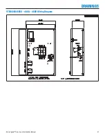
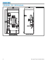
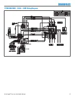
Страница 21: ...Ronk Vigilant Owner s and Installation Manual 21 DRAWINGS VTS04003480SX 400A 480V Wiring Diagram ...
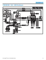
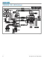
Страница 22: ...22 Ronk Vigilant Owner s and Installation Manual DRAWINGS VTS06003480SX 600A 480V Wiring Diagram ...
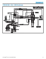
Страница 23: ...Ronk Vigilant Owner s and Installation Manual 23 DRAWINGS VTS04001240SX 400A 240V Wiring Diagram ...
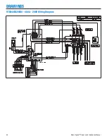
Страница 24: ...24 Ronk Vigilant Owner s and Installation Manual DRAWINGS VTS04003208SX 400A 208V Wiring Diagram ...
Страница 25: ...Ronk Vigilant Owner s and Installation Manual 25 DRAWINGS VTS04003480SX 400A 480V Wiring Diagram ...
Страница 26: ...26 Ronk Vigilant Owner s and Installation Manual DRAWINGS VTS06001240SX 600A 240V Wiring Diagram ...
Страница 27: ...Ronk Vigilant Owner s and Installation Manual 27 DRAWINGS VTS06003208SX 600A 208V Wiring Diagram ...
Страница 28: ...28 Ronk Vigilant Owner s and Installation Manual DRAWINGS VTS06003480SX 600A 480V Wiring Diagram ...


