Manual No. 4801-5163
Replacement Instructions
Door Assembly PCB154 to PCB201
Overview:
There have been internal changes made to the SC-325 & SC-650 Controllers. If it is required that
a door assembly on an existing SC-325 or SC-650 Controller be replaced, there will need to be a
few modifications done during the replacement installation. The majority of the door assembly
will be configured as it is in the current controller and the modifications are listed below.
Disassembling the Old Door Assembly:
To begin, it is recommended that the user go through and take note of the setting on the
controller to allow the door to function as it has previously functioned. Refer to the 4801-5156
controller manual for more information on how to access these settings. There will be several
new program parameters that can be seen on the label of the new door assembly. These new
settings will be listed under “Program Parameters” on the control label. There will also be a
white label sent with the new door assembly that will allow the user to take note of the important
parameters that will need to be set in a later step. Once the parameters are noted on the provided
4501-6106 label as shown in Figure 1, adhere it to the left side of the controller for reference.
Ensure that the power toggle switch on the side of the controller has been positioned to the off
location. With the controller powered down, loosen the two screws on the side and open the door
of the controller. Before proceeding, take note of how the control board is wired (it is
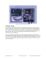
recommended to take a picture for reference as shown in Figure 2). Once the wiring position is
noted, remove the black terminals on the bottom of the control board by pulling up on them until
they slide off the board mounted headers. There will be two white and two red connectors that
will need to be removed as well. Once all the connectors have be removed, cut the zip-tie located
below the control board. Refer to Figure 3.
Figure 1: Program Parameters


