background image


7


USING THE UNIT SAFELY


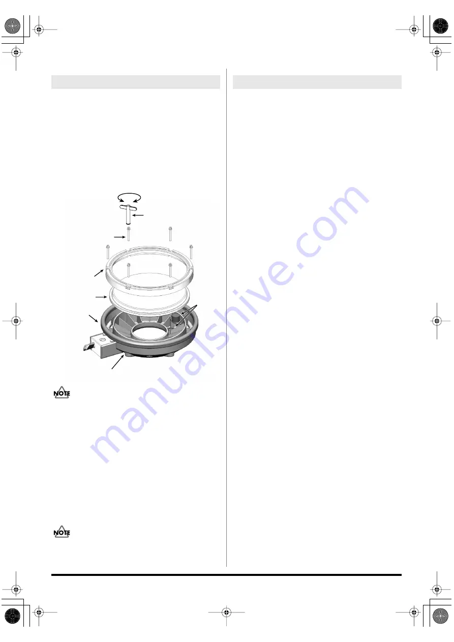
When the Head Should Be Replaced


The head is an expendable item that eventually will wear out 
and need to be replaced. Replace the head when the following 
occurs:

Slack portions remain in the head even when the head tension 
is properly adjusted.


Replacement heads (optional): MH-8 Mesh Head


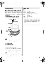
1.


Remove all tuning bolts from the PDX-8.


fig.Replace.e


Do not apply excessive force to the sensor and cushion 
located under the head. Doing so can interfere with 
accurate detection, and may damage it.


2.


Remove the hoop.


3.


Remove the old head.


4.


Place the new head on the shell.


5.


Place the hoop onto the head.


6.


Attach the tuning bolts to the hoop and shell.


7.


Next, adjust the tension of the head. Refer to 

“Adjusting the Head Tension” (p. 5).


Do not firmly tighten a single tuning bolt by itself. Doing 
so will make it impossible to tension the head evenly, and 
will cause malfunctions.


PDX-8


Head Size:

8 inches

Triggers:

2 (Head, Rim)

Dimensions: 266 (W) x 326 (D) x 62 (H) mm

10-1/2 (W) x 12-7/8 (D) x 2-1/2 (H) inches

Weight:

1.3 kg
2 lbs 14 oz

Options:

Mesh Head (MH-8)


* The Rim rubber is one component that eventually wears out 

(the more so if numerous rim shots are performed), and will 
require replacement. Rim shots may not be performed correctly 
when the rim rubber is worn out. If this occurs, replace the rim 
rubber. Consult Roland Service for more on replacing the rim 
rubber.


add


* Due to the nature of the materials used in the sensor, changes 

in room temperature may affect the sensitivity of the sensor.


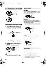
Head Replacement

Tuning Key

Hoop

Hoop’s Rubber 
Portion

Sensor

Loosen

Tighten

Shell

Tuning Bolt

Head


Specifications

TD-3KW_e 7 ページ 2006年1月24日 火曜日 午後6時7分

Содержание V-Compact TD-3KW

Страница 1: ...ut the written permission of ROLAND CORPORATION 201a Before using this unit carefully read the sections entitled USING THE UNIT SAFELY and IMPORTANT NOTES p 2 p 3 These sections provide important info...

Страница 2: ...ith small children an adult should provide supervision until the child is capable of following all the rules essential for the safe operation of the unit 014 Do not drop it 104 Try to prevent cords an...

Страница 3: ...vents of any kind to avoid the possibility of discoloration and or deformation Additional Precautions 553 Use a reasonable amount of care when using the unit s buttons sliders or other controls and wh...

Страница 4: ...make the distance of both Right Left end legs as more than 90cm 36 inches If you do so the stand could fall down Attach the mounting plate included with the optional drum stand to the TD 3 Using the...

Страница 5: ...Strike the head to check the feel and response fig Adjust e Tighten each tuning bolt one by one observing the numerical order shown in the diagram Do not firmly tighten a single tuning bolt by itself...

Страница 6: ...u can play rim shots and or cross stick sounds fig XStick e To play the cross stick be sure that you only strike the rim of the pad Placing your hand on the head of the pad might prevent the cross sti...

Страница 7: ...r to Adjusting the Head Tension p 5 Do not firmly tighten a single tuning bolt by itself Doing so will make it impossible to tension the head evenly and will cause malfunctions PDX 8 Head Size 8 inche...

Страница 8: ...off fig PD HR e PD 8 Pad Size 8 5 inches Triggers 2 Head Rim Dimensions 226 W x 280 D x 54 H mm 8 15 16 W x 11 1 16 W x 2 1 8 H inches Weight 1 2 kg 2 lbs 11 oz PD 8 Tom Attaching the Pad to a Stand S...

Страница 9: ...e sure the ROLAND logo is on the opposite side of the playing area CY 5 Size 10 inches Triggers 2 Bow Edge Dimensions 246 W x 246 D x 45 H mm 9 11 16 W x 9 11 16 D x 1 13 16 H inches Weight 380 g 14 o...

Страница 10: ...e connected trigger input To make use of edge shot you ll need to connect to a trigger input jack on the percussion sound module that accommodates rim shots fig CY Edge e Choking Choking pinching the...

Страница 11: ...th the pedal pressed half way Closed Hi Hat Strike the hi hat with the pedal pressed Foot Closed Completely press down the pedal The volume of the Foot Closed sound can be adjusted separately TD 3 Own...

Страница 12: ...er so that it strikes the center of the head then secure the kick pedal and KD 8 firmly in place fig KD Assy04 e Adjusting the Foot Plate Height Depending on your kick pedal it can be unstable when yo...

Страница 13: ...ake it easier to use the kick pedal However when used on flooring the anchor bolts may damage the floor Adjust the anchor bolts correctly fig KD Anchor e The tips of the anchor bolts are sharp Handle...

Страница 14: ...etting1 e fig Label 1 Insert the plugs of connecting cables into the TRIGGER INPUTS jacks on the rear of the TD 3 2 Insert the L sharped plugs into the TRIGGER OUTPUTS jacks of the pads When you conne...

Страница 15: ...the CY 5 for a 2nd Crash or a Splash Cymbal For mounting use the Cymbal Mount MDY 10U Adding a Tom Adding the PD 8 for a 2nd floor tom For mounting use the Pad Mount MDH 10U Kick Trigger Pad KD 8 KD...

Страница 16: ...caragua TEL 505 277 2557 PANAMA SUPRO MUNDIAL S A Boulevard Andrews Albrook Panama City REP DE PANAMA TEL 315 0101 PARAGUAY Distribuidora De Instrumentos Musicales J E Olear y ESQ Manduvira Asuncion P...

Отзывы: