background image


04348534          1MP

PCR-300_500_800_e.book 100 ページ 2006年12月19日 火曜日 午後2時59分

Содержание EDIROL PCR-300

Страница 1: ...04348534 1MP Owner s Manual Owner s Manual Cover_e fm 1 ページ 2006年12月19日 火曜日 午後5時23分 ...

Страница 2: ... 22 Receiving 22 Saving a control map on your computer 23 Loading a control map 23 Loading a memory set as a control map 23 Importing a memory set 23 Parameter setting items 24 NO ASSIGN 24 Channel Message 24 System Realtime F6 F6 F8 FA FB FC FF 28 System Ex F0 F7 29 Free Message 30 Tempo 30 Playing Play mode 32 Go ahead and play 32 Convenient performance functions 32 Selecting the current channel...

Страница 3: ...bleshooting 82 Problems with connections 82 Deleting the USB driver 84 Problems while using the PCR 85 Appendix 87 Two MIDI ports 88 Connecting the PCR directly to a sound module 89 Control map list 90 MIDI implementation chart 91 Main specifications 92 Index 93 Before using this unit carefully read the sections entitled USING THE UNIT SAFELY and IMPORTANT NOTES separate sheet They provide importa...

Страница 4: ...xtended function for future use For details refer to the Roland website V LINK V LINK is a function that allows music and images to be performed together By using MIDI to connect two or more V LINK compatible devices you can easily enjoy a wide range of visual effects that are linked to the expressive elements of a music performance Panel 1 2 3 4 5 6 7 8 9 10 11 12 13 14 15 16 Indication Summary A...

Страница 5: ...ATA button Use this button when you want to play or make settings for the Lower part If the LOWER button is lit the keyboard notes and aftertouch bender lever pitch bend modulation foot pedal messages and program change messages will be transmitted on the current channel specified for the Lower part Selecting the Lower and Upper sounds p 36 UPPER button CHK SUM button Use this button when you want...

Страница 6: ...s button to switch to decimal input mode p 64 When you re in Play mode this button will function as a conventional controller A9 HEX button When you re not in Play mode you can press this button to switch to hexadecimal input mode p 64 When you re in Play mode p 32 this button will function as a conventional controller B9 Controllers H1 H2 crossfader You can assign the desired MIDI messages to thi...

Страница 7: ...n pedal By connecting any other expression pedals you risk causing malfunction and or damage to the unit Security slot http www kensington com Side panel DC Power turned on when using the AC adaptor OFF Power switched off USB Power turned on when a USB cable is connected You can use the USB i e bus power setting if the PCR 300 500 800 is connected to your computer via a USB cable The power will be...

Страница 8: ...s memory fig CurrentMemory e eps The PCR 300 500 800 holds sixteen control maps in its internal memory In order to use a control map you must copy it into a location called the current memory Any changes you make to the contents of the current memory will be lost when you turn off the power If you want to keep the changes you ve made to the current memory refer to Saving a control map p 9 You can ...

Страница 9: ...g D Edit eps The display will indicate EDIT fig D Save eps 2 Turn the VALUE knob to make the display indicate SAVE fig D Protect eps 3 Press the ENTER button If the display indicates PTC the Protect setting is ON and you ll be unable to save the memory Turn the Protect setting OFF and repeat the procedure from step 1 Protecting the control maps p 13 4 Use the VALUE knob or controllers A1 A8 and B1...

Страница 10: ... will blink in the display Bulk Receive 4 Verify that the display indicates BLR Bulk Receive and then press the ENTER button If the display indicates BLT Bulk Transmit use the VALUE knob to make it indicate BLR Bulk Receive 5 Use the VALUE knob or the controllers to choose the reception method Choose the method that s appropriate for the data you ll be receiving fig D RSBulk Wait eps 6 Verify that...

Страница 11: ...ay will indicate END Press the ENTER button to complete the operation Control map data received as Single Bulk will be loaded into the current memory meaning that it will be lost when you turn off the power However if you save this control map into one of the internal memories you won t need to re transmit it to the PCR Refer to Saving a control map p 9 Error indication If the data was not receive...

Страница 12: ...sion Choose the type of data you want to transmit fig D TSBulk Wait eps 7 Check the indication in the display then press the ENTER button The rightmost digit of the display will blink and the PCR will wait to transmit bulk data 8 Put PCR Editor or your DAW software in recording mode and then press the PCR s ENTER button Data transmission will begin Choose EDIROL PCR 2 as the MIDI input port for PC...

Страница 13: ...ig D Edit eps The display will indicate EDIT fig D Protect eps 2 Turn the VALUE knob to make the display indicate PTC 3 Check the indication in the display then press the ENTER button The display will indicate the current protect status 4 Use the VALUE knob to choose the desired setting and press the ENTER button Protecting the control maps Controller Item Display Explanation A1 0 PROTECT OFF Cont...

Страница 14: ... that follows is for when the PCR is connected via USB If you re using a MIDI connection specify the MIDI input port and MIDI output to which your PCR is MIDI connected instead of EDIROL PCR 2 and EDIROL PCR Setting the MIDI ports What are MIDI ports Input ports The output destination for the MIDI messages sent when you operate the PCR s sliders knobs and buttons can be specified independently for...

Страница 15: ... USB cable to connect the PCR to your Mac then switch on the PCR s power 2 From the Mac Finder open the Applications PCR Editor V2 folder and double click PCR Editor V2 to start up PCR Editor 3 In PCR Editor choose Options MIDI Devices fig MacMIDIPort e eps 4 In the MIDI Devices dialog box make the MIDI device settings shown in the illustration 5 Click OK to close the dialog box Windows users Micr...

Страница 16: ...each controller of the control map currently being edited Edit menu Menu Explanation Copy Copies the setting of the selected controller to the clipboard Paste Pastes the setting from the clipboard to the selected controller NO ASSIGN Sets the assignment of the selected controller to NO ASSIGN Communication menu Menu Explanation Transmit Transmits the control map currently being edited to the curre...

Страница 17: ...ng Keyboard shortcuts Command Windows Macintosh File New Ctrl N Command N File Open Ctrl O Command O File Save Ctrl S Command S File Save As Ctrl Shift S Command Shift S File Exit Alt F4 Command Q Edit Copy Ctrl C Command C Edit Paste Ctrl V Command V Edit NO ASSIGN Del Del Next controller Ctrl F Command F Previous controller Ctrl B Command B PCR 300_500_800_e book 17 ページ 2006年12月19日 火曜日 午後2時59分 ...

Страница 18: ...essage you assign Controller name Shows the name of the controller you re editing Assign Message Lets you select the type of MIDI message to assign to the controller Message assignment fields Here you can specify the value for each parameter of the MIDI message you ve selected in the Assign Message list For details on the parameters of each MIDI message refer to Parameter setting items p 24 Explan...

Страница 19: ...on Port 1 The message will be sent to EDIROL PCR 1 Port 2 The message will be sent to EDIROL PCR 2 Port 1 2 The message will be sent to both EDIROL PCR 1 and EDIROL PCR 2 Mode Explanation Unlatch Switched on when button is pressed switched off when button is released Latch Button acts as a toggle switching on or off each time it s pressed Increase Each time you press the button the value will incr...

Страница 20: ...message that you want to assign fig EH AssignType eps_25 3 According to the type of MIDI message you ve selected set the various parameters in the message assignment area For details on the parameters refer to Parameter setting items p 24 fig EH AssignPort eps_25 4 In the Output Port field specify the MIDI output port 5 If desired use the Comment field to add a comment 6 Click OK Using PCR Editor ...

Страница 21: ... If you want the current settings to be shown on each controller in the main window choose Options Show Messages and add a check mark next to Show Messages This method shows the current settings in simplified form as follows fig EditorViewAssign e eps The color of the indication shows the Output Port setting Viewing the assigned MIDI messages Display Meaning NO ASSIGN Note Channel Pressure Polypho...

Страница 22: ...e data is being transferred When the dialog box disappears transmission has been completed 6 The PCR s display will indicate END Press the PCR s ENTER button to return to Play mode If you want to use PCR Editor to edit a control map that s currently in the PCR keyboard you ll need to load the control map from the PCR s current memory into PCR Editor so that it can be edited Proceed as follows fig ...

Страница 23: ...oaded only from an SMF file that was saved by PCR Editor Here s how to load a control map from an SMF file 1 From the menu bar choose File Open 2 Specify the SMF file that you want to load and click Open A memory set SMF file created for an earlier model in the PCR series can be loaded as a control map for the PCR 300 500 800 Controllers that do not exist on earlier models of the PCR series will b...

Страница 24: ...select the type of message you want to assign According to the message you ve selected set the following parameters Note 9n kk vv Assign a note message fig EditorChannelMessage eps_35 You can specify the following parameters for Note Channel Pressure Dn vv Assign a channel pressure message fig EditorChPres eps_35 You can specify the following parameters for Channel Pressure Parameter setting items...

Страница 25: ... program number fig EditorPC1 eps_35 You can specify the following parameters for Program Change The range of the program number pp is 1 128 Channel Message Item Content MIDI Channel MIDI channel n Note Number Note number kk Min Value Lower value vv of key pressure Max Value Upper value vv of key pressure Item Content MIDI Channel MIDI channel n Control Number Control number cc Min Value Lower lim...

Страница 26: ... range of the program number pp is 1 128 Program Change Dec Assign the program change decrement function PC DEC This will transmit a program change number that is one less than the program change number most recently transmitted in the PCR s program change mode fig EditorPCDec eps_35 There are no parameters to specify for Program Change Dec Channel Message Item Content MIDI Channel MIDI channel n ...

Страница 27: ...nnot be changed NRPN Bn 63 mm Bn 62 ll Bn 06 dm Bn 26 dl Assign a non registered parameter number fig EditorNRPN eps_35 You can specify the following parameters for NRPN The range for the data entry LSB dl is fixed at 0 127 and cannot be changed Channel Message Item Content MIDI Channel MIDI channel n RPN MSB RPN parameter number MSB mm RPN LSB RPN parameter number LSB ll MSB Min Value Lower limit...

Страница 28: ...o anything Assign a system realtime message or F6 Tune Request fig EditorSR eps_35 For System Realtime F6 use the Status field to choose the message you want to assign Channel Message Item Content MIDI Channel MIDI channel n Control Number Controller number cc System Realtime F6 F6 F8 FA FB FC FF Item Content F6 Tune request F8 Timing clock FA Start FB Continue FC Stop FF System reset PCR 300_500_...

Страница 29: ...automatic checksum calculation function use this special character to specify the point at which the check sum is to be inserted and its type S1 The most common type used by Roland and other man ufacturers S2 Choose this if a method other than S1 is used n Channel is any val ue between 0 7 If you want a channel number to be inserted in the exclusive message use this special character to specify it...

Страница 30: ...itations apply to the input You can t use a checksum You can t use a special character as the first byte You can also enter variable data using the special characters de scribed in Table 1 Special characters used in the message entry field p 29 If you use the special character DT use the Data Type field to specify the type of data Data Type If you ve used the special character DT in the message en...

Страница 31: ...31 Using PCR Editor PCR 300_500_800_e book 31 ページ 2006年12月19日 火曜日 午後2時59分 ...

Страница 32: ...gs of the sound module If you assign different MIDI messages to the bender lever the pitch bend effect and modulation effect will not be applied Mode Overview How selected Play mode This is the mode in which you play the key board and operate the controllers MIDI messages will be transmitted by each con troller When you turn on the power When you exit Edit mode Edit mode p 41 This is the mode in w...

Страница 33: ...light and the display will indicate the current channel setting 3 Use controllers A1 A8 or B1 B2 or the VALUE knob to specify the desired channel number 4 Press the ENTER button What is OMNI When you turn the OMNI setting on all controllers will always transmit on the current channel regardless of the MIDI transmit channel that s specified for each individual controller Use the following procedure...

Страница 34: ...elect messages to access more than 128 sounds If you want to select a different sound within the same bank as the currently selected sound you can switch sounds simply by sending a program change message alone If you want to select a sound from a different bank you ll need to send the appropriate bank number and program number The bank number is sent using two MIDI messages control change 0 MSB an...

Страница 35: ...he bank select number that was most recently transmitted 2 Use the VALUE knob to specify the bank select number that you want to send The bank select MSB LSB data has now been transmitted Bank Select Assignments for the VALUE knob Here s how to assign BANK SELECT LSB or BANK SELECT MSB to the USER button of the VALUE knob 1 Press the EDIT button so it s lit The display will indicate EDIT 2 Press t...

Страница 36: ...rd you ll hear the sound you selected for the Upper part Selecting the Lower and Upper sounds Selecting the Lower sound LOWER Selecting the Upper sound UPPER Lower and Upper Use the UPPER button and LOWER button to switch between the Upper part and Lower part When the UPPER button is lit performance data from the keyboard notes and aftertouch bender lever pitch and modulation and foot pedal as wel...

Страница 37: ... play them separately using your left and right hands fig Sprit eps_80 1 Press the DUAL SPLIT button several times to make it blink If you want to change the Upper sound press the UPPER button Layering two sounds Dual Dual LOWER UPPER Playing two sounds in combination Split Split LOWER UPPER Setting the Split point Here s how to specify the Split point at which the Upper and Lower regions will be ...

Страница 38: ...fig H User eps 1 Press the USER button The USER button will light The display will indicate the most recently transmitted velocity value 2 Use the VALUE knob to specify the velocity value tch 1 127 that you want to transmit fig D tch eps If the display indicates tch the transmitted velocity will depend on how strongly you play the keyboard Refer to the system setting Keyboard Velocity Curve p 72 E...

Страница 39: ...if they are moved If a parameter value is distant from the current physical position of a controller you can avoid an unwanted sudden jump in the value by using the PRM MUTE button to mute the controllers before moving the controller to a position that s close to the current value fig H PRMMute eps 1 Press the PRM MUTE button The PRM MUTE button will light and the display will indicate P ON fig D ...

Страница 40: ...on will transmit All Sound Off All Notes Off and Reset All Controllers messages on all channels fig H PANIC eps 1 Simultaneously press the EDIT button and PRM MUTE button The PRM MUTE ENTER button will blink 2 Press the ENTER button The EDIT button and PRM MUTE button will blink several times This completes execution of the Panic function When stuck notes occur Panic Panic PCR 300_500_800_e book 4...

Страница 41: ...l the assignment For details refer to Copy assignment p 66 or Canceling an assignment NO ASSIGN p 67 If you want to assign a single byte system message system realtime message tune request or a freely specified message of up to twenty four bytes refer to System exclusive assign p 55 Assigning MIDI messages on the PCR keyboard Function Display Refer to Note Note assign p 42 Aftertouch Aftertouch as...

Страница 42: ...iting fig D ChannelSelect eps 7 Press the ENTER button The display will indicate CH The portion shows the currently specified value 8 Enter the MIDI transmit channel Use the VALUE knob or controller A1 0 B2 9 to specify the desired channel fig D NoteSelect eps 9 Press the ENTER button The display will indicate N The portion shows the currently specified value 10 Enter the note number Use the VALUE...

Страница 43: ...ENTER button 6 Turn the VALUE knob or press controller A2 1 to make the display indicate NT1 7 Press the ENTER button The display will indicate CH The portion shows the currently specified value 8 Enter the MIDI transmit channel 9 Press the ENTER button The display will indicate N The portion shows the currently specified value 10 Enter the note number 11 Press the ENTER button The display will in...

Страница 44: ...Press the ENTER button The display will indicate CH The portion shows the currently specified value 8 Enter the channel Use the VALUE knob or controllers A1 0 B2 9 to specify the desired channel 9 Press the ENTER button 10 As appropriate for the controller type specify the button mode p 64 Aftertouch assign Edit Controller Display Content MIDI transmit channel Value range Port Button mode Basic ed...

Страница 45: ...the ENTER button 10 If you re using advanced editing 2 or advanced editing 3 enter a note number and press the ENTER button 11 If you re using advanced editing 1 or 3 specify an upper limit and lower limit as described in Specifying the value range upper lower limits p 45 12 If you re using advanced editing 1 or 3 specify the output port Port setting p 65 13 According to the controller type set th...

Страница 46: ...e currently specified value 8 Enter the channel Use the VALUE knob or controllers A1 0 B2 9 to specify the desired channel fig D NoteSelect eps 9 Press the ENTER button The display will indicate N The portion shows the currently specified value 10 Enter the control change number Use the VALUE knob or controllers A1 A8 and B1 B8 to specify the desired control number 11 Press the ENTER button 12 As ...

Страница 47: ...editing 2 you can simulate the operation of a typical rotary encoder If this is assigned to a controller moving the controller to the right of or above the center position will produce the same result as turning the encoder clockwise Similarly moving it to the left of or below the center position will produce the same result as turning the encoder counterclockwise As the controller position moves ...

Страница 48: ...eps 6 Turn the VALUE knob or press controller A1 0 to select the basic editing PC0 indication fig D ChannelSelect eps 7 Press the ENTER button The display will indicate CH The portion shows the currently specified value 8 Enter the channel Use the VALUE knob or controller A1 0 B2 9 to specify the desired channel Program change assign Edit Controller Display MIDI transmit channel Bank MSB Bank LSB ...

Страница 49: ...alue 10 Use the VALUE knob or controllers A1 A8 and B1 B8 to specify the desired program number 11 Press the ENTER button If you ve assigned this basic editing function to R1 R9 S1 S9 or P2 moving the controller to the maximum position will transmit the specified program change message PCR 300_500_800_e book 49 ページ 2006年12月19日 火曜日 午後2時59分 ...

Страница 50: ... advanced editing PC1 indication 7 Press the ENTER button 8 Enter the channel 9 Press the ENTER button 10 Specify the range of values Specifying the value range upper lower limits p 45 Advanced editing 2 Transmitting a bank select 6 Turn the VALUE knob or press controller A3 2 to select the advanced editing PC2 indication 7 Press the ENTER button 8 Enter the channel 9 Press the ENTER button 10 Ent...

Страница 51: ...ress it The display will indicate the number of the controller you selected 3 Check the indication in the display then press the ENTER button 4 Turn the VALUE knob to make PC appear 5 Press the ENTER button 6 Turn the VALUE knob or press controller A4 3 or A5 4 to get PC3 or PC4 to appear in the display 7 Press the ENTER button Program change decrement function PC DEC This lets you transmit a prog...

Страница 52: ...you want to assign Tempo If the controller is a button press it The display will indicate the number of the controller you selected 3 Check the indication in the display then press the ENTER button fig D Tempo eps 4 Turn the VALUE knob to make TMP appear 5 Press the ENTER button 6 Set the button mode p 64 as appropriate for the type of controller For a button the On position specifies the maximum ...

Страница 53: ... blinking in the display The portion shows the currently specified value 8 Enter the channel Use the VALUE knob or controllers A1 0 B2 9 to specify the desired channel 9 Press the ENTER button fig D MSBSelect eps 10 Use the VALUE knob or controllers A1 0 B2 9 to specify the desired RPN MSB CC 101 or NRPN MSB CC 99 The portion shows the currently specified value 11 Press the ENTER button fig D LSBS...

Страница 54: ...n NRPN make NP appear The rest of the procedure is the same as for RPN 5 Press the ENTER button 6 Turn the VALUE knob or press controller A2 1 to select the RP1 indication 7 Press the ENTER button 8 Enter the channel 9 Press the ENTER button 10 Use the VALUE knob or controllers A1 A8 and B1 B8 to specify the RPN MSB CC 101 or the NRPN MSB CC 99 11 Press the ENTER button 12 Use the VALUE knob or co...

Страница 55: ...tem exclusive assign Edit Controller Display Content Value range Ending condition Remarks Limitations Basic editing A1 0 Sys Ex message Range of initial settings Enter F7 First byte fixed at F0 Advanced editing 1 A2 1 Sys Ex message Can be specified Enter F7 First byte fixed at F0 Advanced editing 2 A3 2 1 byte system message 0 5 7 9 D E DATA and CHECKSUM buttons are unavailable Advanced editing 3...

Страница 56: ...ure For details on the actual assignments refer to System exclusive message assignment examples p 58 Using basic editing or advanced editing 1 fig D F0 eps The first byte F0 of the system exclusive message the beginning status will blink This F0 byte cannot be changed 8 Verify that the display is correct and press the ENTER button 9 Use the VALUE knob or controllers A1 A8 and B1 B8 to enter the se...

Страница 57: ...n 10 Use controllers A1 A8 and B1 B8 to enter the first byte 11 Press the ENTER button 12 Enter the second and subsequent bytes in the same way 13 When you ve entered the number of bytes you specified in step 8 the message you entered will be checked to see whether it is a valid MIDI message If there is a problem the display will indicate ERR Press the ENTER button and you ll return to step 8 Ente...

Страница 58: ...hecksum calculation The display will indicate CSS checksum start If you press the CHK SUM button once again CSS will be cancelled 2 Press the ENTER button 3 Continue entering data fig D cs1 eps 4 Press the CHK SUM button at the location at which the checksum should be inserted The display will indicate CS1 checksum type 1 5 Press the ENTER button Checksum types There are two types of checksums as ...

Страница 59: ... cannot be changed 3 Press the ENTER button If you selected DT1 through DT4 the display will indicate DT 4 Press the ENTER button Data number Data type Default range Target of range setting Example specified minimum and maximum value DT0 7bit 00H 7FH Specify the data range 00H 7FH 04 45 minimum 4H maximum 45H DT1 4bit 4bit 0H 0H FH FH Specify the range of the first byte 0H FH Second byte is fixed ...

Страница 60: ...enience For a specific example refer to system exclusive assign Bend Pitch Control p 63 1 At the location where you want the channel block number to be inserted press the DATA button several times to select 0CH for the channel or 0BL for the block fig chbl eps_70 The portion shows the currently specified value 2 Use controllers A1 A8 to enter the value of the upper four bits The 0 in the display w...

Страница 61: ...st byte F0 beginning status of the system exclusive message This cannot be changed 8 Check the indication in the display then press the ENTER button 9 Use controllers A8 7 and B7 E to enter the second byte 7E You can also use the VALUE knob to change the value 10 Check the indication in the display then press the ENTER button 11 Use controllers A8 7 and B8 F to enter the third byte 7F You can also...

Страница 62: ...hanged 8 Check the indication in the display then press the ENTER button 9 Use controllers A8 7 and B8 F to enter the second byte 7F 10 Check the indication in the display then press the ENTER button 11 In the same way enter the third byte 7F fourth byte 04 and fifth byte 01 12 Since the sixth byte is the data area press the DATA button and then press controller A4 3 The display will indicate DT3 ...

Страница 63: ...checksum start will be blinking in the display 13 Check the indication in the display then press the ENTER button 14 Next enter the sixth byte 15 Since the seventh byte will have 2 as the upper bits and the block number as the lower bits press DATA three times The display will indicate 0BL 16 Press pad 2 to specify 2 as the upper bits The display will indicate 2BL 17 Check the indication in the di...

Страница 64: ... button is to operate the button mode When you use a button as a controller the maximum specified value will be transmitted when you turn the button on and the minimum value will be transmitted when you turn the button off 1 Turn the VALUE dial to select either Unlatch Latch or Increase mode 2 Press the ENTER button Mode Display Summary Unlatch The button will turn on when pressed and off when rel...

Страница 65: ...m the minimum to maximum On The value will remain at the center value 64 near the middle of the controller s range 64 0 127 63 65 Port setting When using edit mode to assign MIDI messages on the PCR keyboard p 41 and you ve selected advanced editing you ll need to specify the USB port from which the message assigned to the controller will be transmitted when using a USB connection 1 Turn the VALUE...

Страница 66: ...t will not operate Please be aware of the controller type and content of the message when copying MIDI message assignments fig H Edit eps 1 Press the EDIT button so it s lit fig D Edit eps The display will indicate EDIT fig D r1 eps 2 Select the copy destination controller and move it slightly If it s a button press it The display will indicate the controller number 3 Check the indication in the d...

Страница 67: ...t channel fig H Edit eps 1 Press the EDIT button so it s lit fig D Edit eps The display will indicate EDIT fig D r1 eps 2 Select the controller whose message assignment you want to cancel and move it slightly If it s a button press it The display will indicate the controller number 3 Check the indication in the display then press the ENTER button fig D NoAssign eps 4 Turn the VALUE knob to get the...

Страница 68: ...transmitted when F8 Clock On Off is on PORT 1 p 71 Keyboard A4 3 KEYBOARD VELOCITY CURVE Specifies the response curve for the velocity that is transmitted when you play the keyboard 1 MEDIUM p 72 A5 4 KEYBOARD PORT SET Specifies the port from which the keyboard and bender lever will transmit performance data PORT 1 p 74 A6 5 KEYBOARD AFTERTOUCH CURVE Specifies the response curve for keyboard after...

Страница 69: ...which control map will be loaded at startup when the PCR is powered up CONTROL MAP No 0 p 79 Controller A2 1 A5 4 VALUE ENCODER Specifies the parameter that the VALUE knob will transmit KEY VELOCITY p 80 A2 1 A6 5 DYNAMIC MAPPING V LINK Specifies the function of the DYNAMIC MAPPING V LINK switch DYNAMIC MAPPING 0 p 81 Other A2 1 A4 3 H ACTIVITY ON OFF Turn this on if you re using the PCR with cert...

Страница 70: ... tempo of the F8 Clock when F8 Clock is On After you turn on the power this tempo will be transmitted until you move the VALUE knob to which Tempo is assigned Tempo assign p 52 1 Press the EDIT button so it s lit The display will indicate EDIT 2 Use the VALUE knob to select SYS and press the ENTER button 3 Use the VALUE knob to select SY01 and press the ENTER button 4 Use the VALUE knob to set the...

Страница 71: ... and press the ENTER button 4 Use the VALUE knob or controllers A1 A3 to specify the F8 Clock Port The display will indicate the port you specify 5 Press the ENTER button to return to Play mode F8 Clock Port Set Controller Indication Setting Summary A1 0 PORT 1 The clock will be sent to EDIROL PCR 1 A2 1 PORT 2 The clock will be sent to EDIROL PCR 2 A3 2 PORT 1 2 The clock will be sent to EDIROL P...

Страница 72: ...of curve Keyboard sensitivity A1 0 1 LIGHT These are the most typical velocity curves The volume will correspond to your key board playing strength in the most natural way You can produce high velocity values volumes even by playing the keyboard softly A2 1 1 MEDIUM The keyboard sensitivity will be normal A3 2 1 HEAVY You will need to play strongly in order to produce high velocity values volumes ...

Страница 73: ...will need to play strongly in order to produce high velocity values volumes B2 9 4 LIGHT Compared to curve 1 these curves produce greater volume change across the strongly played range of notes You can produce high velocity values volumes even by playing the keyboard softly B3 A 4 MEDIUM The keyboard sensitivity will be normal B4 B 4 HEAVY You will need to play strongly in order to produce high ve...

Страница 74: ... Keyboard Aftertouch Curve The display will show the setting you specified 5 Press the ENTER button to return to Play mode Keyboard Port Set Controller Indication Setting Summary A1 0 PORT 1 Messages will be sent to EDIROL PCR 1 A2 1 PORT 2 Messages will be sent to EDIROL PCR 2 A3 2 PORT 1 2 Messages will be sent to EDIROL PCR 1 and EDIROL PCR 2 Keyboard Aftertouch Curve Controller Indication Sett...

Страница 75: ...ty Curve Controller Indication Setting Curve type Effect A1 0 1 This is the most typical set ting It will produce the most natural correspondence be tween the force of your pad strike and the change in vol ume A2 1 2 Compared to curve 1 this al lows more volume change to be produced in the softer range of pad strikes A3 2 3 This curve produces less vol ume change in response to your pad strikes ma...

Страница 76: ...een the PCR and the computer or between the PCR and the external MIDI device A2 1 ON The MIDI connectors of the PCR keyboard will operate as a MIDI interface MIDI messages from the computer that s connected via USB to the PCR will be conveyed to the sound module connected to the PCR s MIDI OUT connector MIDI messages from the MIDI device connected to the PCR s MIDI IN connector will be con veyed t...

Страница 77: ...o Play mode MIDI Merge Destination Controller Indication Setting Summary A1 0 PORT 1 Messages from MIDI IN will be merged with the PCR s PORT 1 A2 1 PORT 2 Messages from MIDI IN will be merged with the PCR s PORT 2 A3 2 MIDI OUT Messages from MIDI IN will be merged with the PCR s MIDI OUT The MIDI MERGE switch and the MIDI Merge Destination In this diagram the MIDI MERGE switch is ON and the MIDI ...

Страница 78: ... USB MIDI driver type FPT Fast Processing Technology of MIDI Transmission This makes effective use of the USB bandwidth depending on the amount of MIDI data being sent ensuring that MIDI data handling will always occur optimally 5 Press the ENTER button to return to Play mode Advanced Driver Switch Controller Indication Setting Summary A1 0 OFF Choose this setting if you want to use the standard M...

Страница 79: ... 4 Use the VALUE knob or controllers A1 or A2 to choose CONTROL MAP No 0 or LAST ACCESS MEMORY 5 Press the ENTER button Control map settings Startup Memory Controller Indication Setting Summary A1 0 CONTROL MAP No 0 Control map number 0 will be load ed into current memory p 8 when the PCR starts up A2 1 LAST ACCESS MEMORY The control map that you most re cently called up or saved will be loaded in...

Страница 80: ... by the VALUE knob regardless of how strongly you play the keyboard Use this in cases where you want to eliminate dynamics from your playing tch 1 127 If you specify tch velocity values corresponding to your keyboard playing strength will be transmitted A2 1 BANK LSB The VALUE knob will specify the bank select LSB CC 32 0 127 A3 2 BANK MSB The VALUE knob will specify the bank select MSB CC 00 0 12...

Страница 81: ...ess the ENTER button 4 Use the VALUE knob to turn H activity on or off The display will indicate ON or OFF 5 Press the ENTER button Here s how to restore the settings of the PCR keyboard to the state they were in when the product shipped from the factory 1 Press the EDIT button so it s lit The display will indicate EDIT 2 Use the VALUE knob to select SYS and press the ENTER button 3 Use the VALUE ...

Страница 82: ...s USB hubs that do not contain a power supply Please use a self powered hub a hub that contains a power supply Could another USB device be connected All USB devices other than a mouse and keyboard must be disconnected from your computer before you install the driver Could other applications or resident software such as antivirus programs be running Installation may not occur correctly if other pro...

Страница 83: ...ect to Windows Update choose No and click Next 2 Choose Install the software automatically recommended and click Next If a dialog box with a or X symbol appears click Continue to proceed with installation If you are unable to proceed click OK and re install the driver Windows 2000 users If a dialog box that says Unable to find digital signature appears click Yes to proceed with installation If you...

Страница 84: ... Select the DRIVER XP2K folder 5 Double click the UNINSTAL icon 6 Proceed with the uninstallation as directed by the instructions that appear Mac OS X users 1 Start up your Mac with the PCR disconnected Make sure that all USB cables except those for a USB keyboard and USB mouse are disconnected 2 Insert the CD ROM into your Mac s CD ROM drive 3 In the Driver folder of the CD ROM double click PCR_U...

Страница 85: ...ror messages may appear if you are running multiple items of software at the same time If so close the software you re not using If the software is still shown in the Windows taskbar after you ve closed the window the software is still running Close all unneeded software shown in the taskbar Could a heavy processing load have occurred while using the PCR such as accessing the CD ROM drive or netwo...

Страница 86: ...tings in your DAW software to enable the function that passes system exclusive messages through to your sound module For details on how to enable this refer to the owner s manual for your software The PCR lets you assign MIDI messages to the bender and modulation controllers of the bender lever If such assignments have been made the lever won t produce pitch bend or modulation Set the bender and m...

Страница 87: ...87 Appendix PCR 300_500_800_e book 87 ページ 2006年12月19日 火曜日 午後2時59分 ...

Страница 88: ...er section of the DAW software Since the PCR has two MIDI output ports you can use one port to play sounds and control the sound module while using the other port to control your DAW software fig MIDI port3 e eps_55 For example if you want to use the PCR s A1 A9 and B1 B9 buttons to switch sounds on your sound module and use the S1 S9 sliders to control the volume faders of your DAW software s mix...

Страница 89: ...MIDI OUT connector to the MIDI IN connector of your MIDI sound module 2 Connect the AC adaptor to the PCR s DC IN jack 3 Set the PCR s power switch to DC to turn on the power Also switch on the power to your MIDI sound module 4 Set the PCR s current channel to match the MIDI receive channel of your MIDI sound module 5 When you play the keyboard your MIDI sound module will produce sound Make sure t...

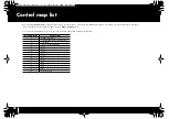
Страница 90: ... Refer to Using control maps p 8 You can also download the latest control maps from the Roland website and load them into the PCR Memory Number Factory Setting 0 DYNAMIC MAPPING 0 1 SONAER LEÅASONAR 5 MCR 8 Mode3 2 GarageBand 3 Cubase 3 SX MCR 8 Mode4 4 Logic 7 5 Logic 7 6 Logic 7 7 Logic 7 8 Logic 7 9 Logic 7 10 Logic 7 11 B4 II 12 B4 II 13 B4 II 14 GM 15 motion dive tokyo PCR 300_500_800_e book ...

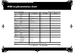
Страница 91: ...une Clock Command All Sound Off Reset All Controller Local control All Notes Off Active Sense Reset 1 1 16 Mode 3 OMNI ON OFF MONO POLY O 9n v 1 127 O 8n v 1 127 9n v 0 0 127 O O O O X O 0 127 O O O 0 127 O O O O 1 120 O 1 121 O O 1 123 O O X X X X X X X X X X X X X X O X X X X X X X X X X X 1 Transmits When the Panic function is executed Model PCR 300 500 800 Date Jan 01 2007 Version 1 00 Mode 1 ...

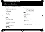
Страница 92: ...ptor or USB Bus Power Current Draw 300mA AC Adaptor 300mA USB Bus Power Dimensions PCR 300 605 9 W x 250 8 D x 91 4 H mm 23 7 8 W x 9 7 8 D x 3 5 8 H inches PCR 500 838 9 W x 250 8 D x 91 4 H mm 33 1 16 W x 9 7 8 D x 3 5 8 H inches PCR 800 1001 9 W x 250 8 D x 91 4 H mm 39 1 2 W x 9 7 8 D x 3 5 8 H inches Weight PCR 300 2 9 kg 6 lbs 7 oz PCR 500 3 8 kg 8 lbs 7 oz PCR 800 4 5 kg 9 lbs 15 oz Accesso...

Страница 93: ...ulk Receive 10 Bulk Transmit 12 Button Mode 19 64 Buttons 6 C CANCEL Button 5 Channel 60 Channel Message 24 28 Channel Pressure 24 Checksum 58 CHK SUM Button 5 Clock 70 Comment 19 Communication Menu 16 CONTROL CHANGE 80 Control Change 25 Control Change Assign 46 Control Map 8 23 79 Loading 23 Protecting 13 Receiving 10 Saving 9 12 23 Switching 9 CONTROL MAP Button 5 Control Map List 90 Controllers...

Страница 94: ...EDIROL PCR MIDI OUT 14 EDIT Button 5 Edit Menu 16 Edit Mode 41 Encoder Simulate 28 ENTER Button 5 F F6 28 F8 Clock Default Tempo 70 F8 Clock On Off 70 F8 Clock Port Set 71 Factory Reset 81 File Menu 16 Free Message 30 G GM2 System On 61 H H activity On Off 81 Help Menu 16 HEX Button 6 I Increase 19 64 Input Mode 64 Input Port 14 K KEY VELOCITY 80 Key Velocity 38 Keyboard 72 Keyboard Aftertouch Cur...

Страница 95: ...ssages 41 MIDI Port 14 88 MIDI Sound Module 89 MIDI Transmit Channel 33 Modulation 32 N NO ASSIGN 16 18 24 67 Note 24 Note Assign 42 NRPN 27 53 O OCTAVE Buttons 5 32 Octave Shift 32 OMNI 33 OMNI OFF 33 OMNI ON 33 Options Menu 16 Output Port 14 19 P Pad Aftertouch Curve 75 Pad Velocity Curve 75 Pads 6 75 Panic 40 PC DEC 51 PC INC 51 PCR Editor 14 Pitch Bend 32 Play Mode 32 Polyphonic Key Pressure 2...

Страница 96: ...nt 37 Startup Memory 79 System Ex 29 System Exclusive Assign 55 System Exclusive Message 29 System Realtime Message 28 System Settings 68 T TEMPO 80 Tempo 30 Tempo Assign 52 Title 18 Two Sounds Layering 37 U Unlatch 19 64 UPPER Button 5 36 Upper Limit 45 Upper Sound 36 Upper Lower Limits 45 USB 4 7 USB Connector 7 USB Driver 84 USER Button 5 V VALUE Encoder 80 VALUE Knob 5 35 38 80 Value Range 45 ...

Страница 97: ... assignment NO ASSIGN Controllers Setting the Split point p 37 Saving a control map p 9 What is OMNI p 33 Protecting the control maps p 13 System settings p 68 Receiving a control map from your computer Bulk Receive p 10 Saving control map data on your computer Bulk Transmit p 12 p 42 p 44 p 46 p 48 p 53 p 53 p 55 p 52 p 67 PCR 300_500_800_e book 97 ページ 2006年12月19日 火曜日 午後2時59分 ...

Страница 98: ...Memo PCR 300_500_800_e book 98 ページ 2006年12月19日 火曜日 午後2時59分 ...

Страница 99: ...l Bahrain Avenue P O Box 247 Manama 304 State of BAHRAIN TEL 17 211 005 IRAN MOCO INC No 41 Nike St Dr Shariyati Ave Roberoye Cerahe Mirdamad Tehran IRAN TEL 021 285 4169 ISRAEL Halilit P Greenspoon Sons Ltd 8 Retzif Ha aliya Hashnya St Tel Aviv Yafo ISRAEL TEL 03 6823666 FINLAND Roland Scandinavia As Filial Finland Elannontie 5 FIN 01510 Vantaa FINLAND TEL 0 9 68 24 020 GERMANY Roland Elektronisc...

Страница 100: ...04348534 1MP PCR 300_500_800_e book 100 ページ 2006年12月19日 火曜日 午後2時59分 ...

Отзывы: