18
Mar. 2008
GT-10
5.
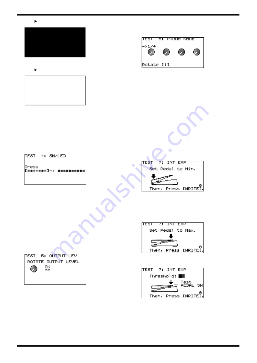
Press [
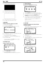
] to display the screen shown below.
fig.3lcdenc3.eps
6.
Verify that the LCD screen has no missing dots.
7.
Press [
] to display the screen shown below.
fig.3lcdenc4.eps
8.
Verify that the lines on the four sides are unbroken.
9.
Press [EXIT] to return to the test-item select screen.
4. SW/LED
Testing of Operation Switches and LEDs
1.
Use the dial to choose
4: SW/LED
.
2.
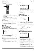
Press [CATEGORY/ENTER] to display the screen shown below.
fig.4swlcd2e.eps
3.
If ########## appears, verify that the corresponding LED is illuminated.
4.
Press the button indicated by *******.
* Pressing a wrong button makes the message
NG!
appear.
5.
If ########## appears, verify that the corresponding LED goes dark.
6.
Repeat steps
3
through
5
.
When as the final item the LED for
PEDAL 1
goes dark, execution
automatically advances to the next test.
5. OUTPUT LEV
Testing of the OUTPUT Control
fig.5outputlev2.eps
1.
Turn the
OUTPUT LEVEL
control to minimum.
2.
Turn the
OUTPUT LEVEL
control to maximum.
If
OK
is displayed, execution automatically advances to the next test.
6. PARAM KNOB
Testing of the PARAMETER Controls
fig.6paramknob2.eps
1.
Turn the
PARAMETER 1
control clockwise by 360 degrees or more.
2.
Verify that the these values are displayed:
1/4 -> 2/4 -> 3/4 -> 4/4 -> OK
.
3.
In the same way, successively turn the
PARAMETER 2
through
PARAMETER 4
controls clockwise by 360 degrees or more.
4.
Verify that the these values are displayed:
1/4 -> 2/4 -> 3/4 -> 4/4 -> OK
.
* Turning too rapidly may cause the correct results to fail to be displayed.
* Turning two or more controls at the same time causes
NG
(not OK) to be
displayed. Turn one at a time.
If
OK
is displayed, execution automatically advances to the next test.
7. INT EXP
Testing of the Expression Pedal and Pedal-
calibration Settings
* The CPU A/D value is displayed for identification of defect factors. No special
verification is required during the course of the procedures.
fig.7intexp2.eps
1.
Depress the heel of the GT-10’s expression pedal all the way, then press
the [WRITE] button.
2.
Verify that
OK
is displayed.
3.
In the same way, depress the toe of the expression pedal all the way, then
press the [WRITE] button.
fig.7intexp3.eps
4.
Verify that
OK
is displayed.
Execution advances to the screen shown below.
fig.7intexp4.eps
Содержание Boss GT-10
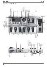
Страница 4: ...4 Mar 2008 GT 10 Location of Controls fig panel GT 10 eps...
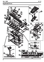
Страница 6: ...6 Mar 2008 GT 10 Exploded View fig bunkai eps L...
Страница 7: ...7 Mar 2008 GT 10 fig bunkai eps R...
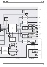
Страница 11: ...11 Mar 2008 GT 10 fig block wiring eps R...
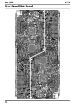
Страница 24: ...24 Mar 2008 GT 10 Circuit Board Main Board fig b main 1 eps...
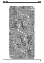
Страница 25: ...25 Mar 2008 GT 10 fig b main 2 eps...
Страница 26: ...26 Mar 2008 GT 10 Circuit Diagram Main Board 1 5 fig d main 1 eps L...
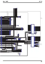
Страница 27: ...27 Mar 2008 GT 10 fig d main 1 eps R...
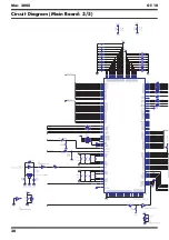
Страница 28: ...28 Mar 2008 GT 10 Circuit Diagram Main Board 2 5 fig d main 2 eps L...
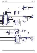
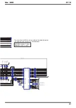
Страница 29: ...29 Mar 2008 GT 10 fig d main 2 eps R...
Страница 30: ...30 Mar 2008 GT 10 Circuit Diagram Main Board 3 5 fig d main 3 e eps L...
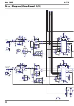
Страница 32: ...32 Mar 2008 GT 10 Circuit Diagram Main Board 4 5 fig d main 4 eps L...
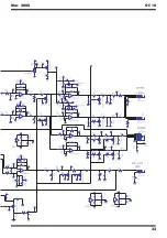
Страница 33: ...33 Mar 2008 GT 10 fig d main 4 eps R...
Страница 34: ...34 Mar 2008 GT 10 Circuit Diagram Main Board 5 5 fig d main 5 eps L...
Страница 35: ...35 Mar 2008 GT 10 fig d main 5 eps R...
Страница 36: ...36 Mar 2008 GT 10 Circuit Board SW VR Pedal Bank ENC EXP Board fig b sw 1 eps...
Страница 37: ...37 Mar 2008 GT 10 fig b sw 2 eps...
Страница 38: ...38 Mar 2008 GT 10 Circuit Diagram SW VR Board fig d sw vr eps L...
Страница 39: ...39 Mar 2008 GT 10 fig d sw vr eps R...
Страница 40: ...40 Mar 2008 GT 10 Circuit Diagram Pedal Board fig d pedal eps L...
Страница 41: ...41 Mar 2008 GT 10 fig d pedal eps R...
Страница 42: ...42 Mar 2008 GT 10 Circuit Diagram Bank Board fig d bank eps Circuit Diagram ENC Board fig d enc eps...
Страница 44: ...MEMO Mar 2008 GT 10...

