Troubleshooting
R&S
®
TSME-Z3
19
Getting Started 1519.0994.02 ─ 02
3. Switch the system unit back on.
To check the USB connectors
1. Connect a control PC to the "Host" or "CPU" connectors on the system unit.
2. Connect an external device to one of the USB connectors on the system unit.
3. Check whether the USB device is detected by the control PC.
4.1
Status LEDs
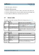
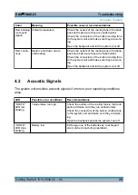
The system unit provides two status LEDs on the front panel (see
Table 4-1: PWR LED
Color
Meaning
Possible causes/ recommendations
Off
No power supplied to the sys-
tem
Connect external power supply or battery and
Green
Unit is supplied with power
Yellow
Standby due to internal error
Internal power failure or shut down due to over-
heating; check power connections and cooling
system
Table 4-2: STATE LED
Color
Meaning
Possible causes/ recommendations
White
Self test is being performed
Wait a few seconds until self test has completed.
Green
System powered from exter-
nal DC supply
Blue
System powered from internal
batteries
Blue, blink-
ing (+acous-
tic signal)
Battery low
Exchange one of the batteries by a recharged
one (can be done during operation).
Status LEDs


