


Operating the instrument
R&S
®
FE50DTR
30
Manual 1179.3180.02 ─ 02
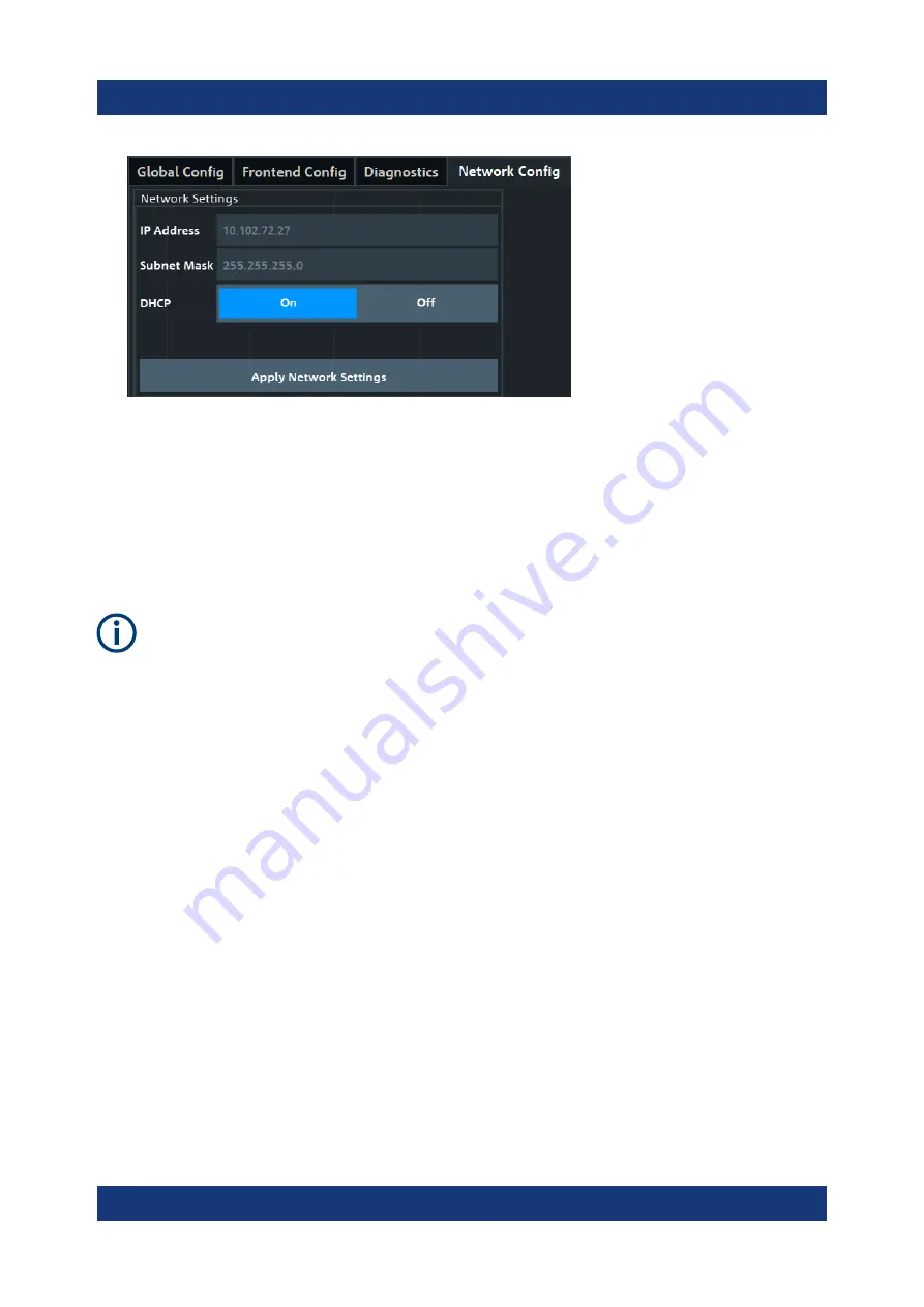
By default, DHCP is enabled and the IP address of the external frontend is
assigned automatically.
9. Optionally, if you need to change the network settings, proceed as follows:
a) Disable DHCP ("DHCP" > "Off").
b) Adjust the network settings according to your test setup.
c) Click "Apply Network Settings".
If you change the network configuration to "DHCP" > "On", the connection to
the R&S
FE50DTR is aborted. You must re-establish a connection to the
frontend as in step 4).
If you have connection issues, see section „Troubleshooting External Frontend
Control“ in the R&S
FSV/A user manual.
To configure frequency settings at the vector signal analyzer
This step-by-step description explains how the R&S
FSV/A configures frequency
settings at the R&S
FE50DTR. Test setups typically require a defined setting of
the frequency band configuration at the R&S
FE50DTR. Configure this setting in
the "Frontend Config" dialog of R&S
FSV/A.
1. To define IF range and internal LO of the R&S
FE50DTR, set the "Frequency
Band Config" mode:
● "IF High": A higher IF is used on the external frontend, resulting in a higher
IF input frequency at the R&S
FSV/A.
Use this setting, e.g., if you need an extended analysis bandwidth (>
400
MHz) at the vector signal analyzer (option B1000).
● "IF Low": A lower IF is used on the external frontend, resulting in a lower IF
input frequency at the R&S
FSV/A.
Operating the R&S
FE50DTR in Rx mode


