R&S
®
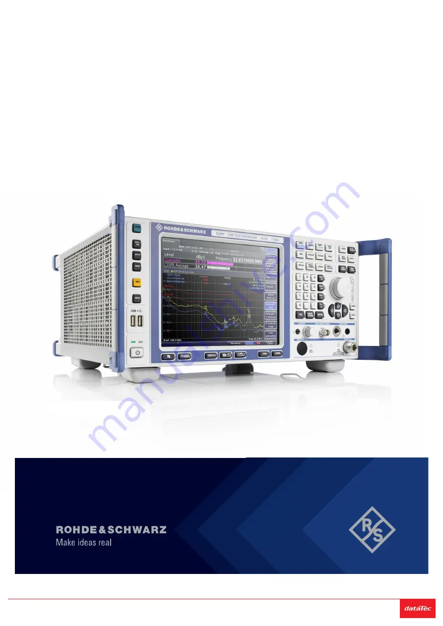
ESRP
EMI Test Receiver
Getting Started
1316469702Version 07
(=@^ï2)
Sie haben Fragen oder wünschen eine Beratung?
Angebotsanfrage unter
+49
7121 / 51 50 50
oder über
info@datatec.
eu
Distributed by:
Страница 1: ...R S ESRP EMI Test Receiver Getting Started 1316469702 Version 07 ï2 Sie haben Fragen oder wünschen eine Beratung Angebotsanfrage unter 49 7121 51 50 50 oder über info datatec eu Distributed by ...
Страница 2: ...any Phone 49 89 41 29 0 Email info rohde schwarz com Internet www rohde schwarz com Subject to change data without tolerance limits is not binding R S is a registered trademark of Rohde Schwarz GmbH Co KG Trade names are trademarks of the owners 1316 4697 02 Version 07 R S ESRP Throughout this manual products from Rohde Schwarz are indicated without the symbol e g R S ESRP is indicated as R S ESRP...
Страница 3: ...y Procedures 17 2 5 Basic Safety Instructions 17 2 6 Data Sheets and Brochures 17 2 7 Release Notes and Open Source Acknowledgment OSA 17 2 8 Application Notes Application Cards White Papers etc 18 3 Conventions Used in the Documentation 19 3 1 Typographical Conventions 19 3 2 Conventions for Procedure Descriptions 19 3 3 Notes on Screenshots 20 4 Instrument Tour 21 4 1 The Front Panel 21 4 1 1 To...
Страница 4: ...Out 30 4 2 7 GPIB Interface 30 4 2 8 Trigger Output 30 4 2 9 IF Video 30 4 2 10 USB 31 4 2 11 AUX Port 31 4 2 12 OCXO option R S FSV B4 31 4 2 13 Device ID 32 5 Preparing For Use 33 5 1 Lifting and Carrying 33 5 2 Unpacking and Checking 33 5 3 Choosing the Operating Site 34 5 4 Setting up the R S ESRP 34 5 5 Placing the R S ESRP on a Bench Top 35 5 6 Mounting the R S ESRP in a Rack 36 5 7 Connecti...
Страница 5: ...s 49 6 1 Information in the Diagram Area 49 6 1 1 Channel Display 50 6 1 2 Display of Hardware Settings 51 6 1 3 Measurement Settings Information 52 6 1 4 Diagram specific and Trace Information 54 6 1 5 Instrument and Status Information 56 6 2 Means of User Interaction 57 6 2 1 Toolbar 58 6 2 2 Touchscreen 59 6 2 3 On screen Keyboard 60 6 2 4 Keypad 61 6 2 5 Rotary Knob 62 6 2 6 Arrow Keys UNDO RE...
Страница 6: ...aying and Setting the Date and Time 81 6 4 11 Changing the Display Update Rate 81 7 Basic Measurement Examples 83 7 1 Measuring a Sinusoidal Signal 83 7 1 1 Measuring the Level and Frequency Using Markers 84 7 1 2 Measuring the Signal Frequency Using the Frequency Counter 87 7 2 Measuring Harmonics of Sinusoidal Signals 88 7 3 Measuring Signal Spectra with Multiple Signals 92 7 3 1 Separating Sign...
Страница 7: ...g FM Modulated Signals 107 7 5 Storing and Loading Instrument Settings 111 7 5 1 Storing an Instrument Configuration without Traces 111 7 5 2 Storing Traces 112 7 5 3 Loading an Instrument Configuration with Traces 112 7 5 4 Configuring Automatic Loading 113 Index 114 ...
Страница 8: ...Contents R S ESRP 8 Getting Started 1316 4697 02 07 ...
Страница 9: ...ame information is provided in many languages as printed Safety Instructions The printed Safety Instructions are delivered with the product Throughout the documentation safety instructions are provided when you need to take care during setup or operation 1 1 Safety Instructions Products from the Rohde Schwarz group of companies are manufactured according to the highest technical standards To use t...
Страница 10: ...ou can use lifting or transporting equipment such as lift trucks and forklifts Follow the instructions provided by the equipment manu facturer Choosing the operating site Only use the product indoors The product casing is not waterproof Water that enters can electrically connect the casing with live parts which can lead to elec tric shock serious personal injury or death if you touch the casing If...
Страница 11: ...the power adapter does not adjust automatically set the correct value and check the rating of the fuse If a product has an exchangeable fuse its type and characteristics are indica ted next to the fuse holder Before changing the fuse switch off the instrument and disconnect it from the power source How to change the fuse is described in the product documentation Only use the power cable delivered ...
Страница 12: ...ly the battery contents are potentially hazardous As long as a battery is undamaged and the seals remain intact there is no danger Impact shock or heat can cause damage such as dents punctures and other deformations A damaged battery poses a risk of personal injury Handle a dam aged or leaking battery with extreme care Immediately ventilate the area since the battery releases harmful gases If you ...
Страница 13: ...s the severity of the defect When returning batteries or Rohde Schwarz products containing batteries use a carrier qualified to transport dangerous goods and notify the car rier of this classification Follow the carrier s transport stipulations in line with IATA DGR IMDG Code ADR or RID Connecting headphones Take the following measures to prevent hearing damage Before using head phones check the v...
Страница 14: ...uct contains a laser Avoid exposure to direct or reflected laser beam 1 2 Warning Messages in the Documentation A warning message points out a risk or danger that you need to be aware of The signal word indicates the severity of the safety hazard and how likely it will occur if you do not follow the safety precautions WARNING Potentially hazardous situation Could result in death or serious injury ...
Страница 15: ...and Regulatory Information R S ESRP 15 Getting Started 1316 4697 02 07 1 3 Korea certification class A 이 기기는 업무용 A급 전자파 적합기기로서 판매자 또는 사용자는 이 점을 주의하 시기 바라며 가정외의 지역에서 사용하는 것을 목적으로 합니다 Korea certification class A ...
Страница 16: ...r Manuals and Help Contains the description of all instrument modes and functions It also provides an introduction to remote control a complete description of the remote control commands with programming examples and information on maintenance instru ment interfaces and error messages Includes the contents of the getting started manual The contents of the user manuals are available as help in the ...
Страница 17: ...ent is delivered with the instrument 2 6 Data Sheets and Brochures The data sheet contains the technical specifications of the R S ESRP It also lists the options and their order numbers as well as optional accessories The brochure provides an overview of the instrument and deals with the specific characteristics www rohde schwarz com brochure datasheet esrp 2 7 Release Notes and Open Source Acknow...
Страница 18: ...ohde schwarz com firmware esrp 2 8 Application Notes Application Cards White Papers etc These documents deal with special applications or background information on particular topics www rohde schwarz com application esrp Application Notes Application Cards White Papers etc ...
Страница 19: ...played in italics Links Links that you can click are displayed in blue font References References to other parts of the documentation are enclosed by quotation marks 3 2 Conventions for Procedure Descriptions When operating the instrument several alternative methods may be available to perform the same task In this case the procedure using the touchscreen is described Any elements that can be acti...
Страница 20: ...are meant to illustrate as many as possible of the provided functions and possible interdependencies between parameters The shown values may not represent realistic usage scenarios The screenshots usually show a fully equipped product that is with all options installed Thus some functions shown in the screenshots may not be available in your particular product configuration Notes on Screenshots ...
Страница 21: ...hown in Figure 4 1 Each element function keys and connectors is described in more detail in the subsequent sections Figure 4 1 Front panel of the R S ESRP 1 Function keys 2 USB interface 3 Power button 4 Display 5 Access to operating system and online keyboard 6 Display options 7 Navigation options for menus 8 Measurement configuration 9 Marker functions 10 Measurement control 11 Measurement start...
Страница 22: ... RF input 2 22 RF input 1 4 1 1 Touchscreen Display The touchscreen on the front panel of the R S ESRP displays the measurement results Additionally the screen display provides status and setting information and allows you to switch between various measurement tasks The screen is touch sensitive offering an alternative means of user interaction for quick and easy handling of the instrument Figure ...
Страница 23: ...screen is tapped by a finger or a pointing device for example Any user interface elements that can be clicked on by a mouse pointer can also be tapped on the screen to trigger the same behavior and vice versa Using the touchscreen the following tasks among others can be performed by the tap of your finger Changing a setting Changing the display Moving a marker Selecting a new evaluation method Scr...
Страница 24: ...board on and off Repeatedly pressing the key changes the position of the keyboard top or bottom of the display Selects alphanumeric characters Opens a dialog box to turn screen elements on or off Switches between maximized and split display of focus area Switches focus area between table and diagram Allows you to define and use softkeys to load custom configurations Opens the root menu of the curr...
Страница 25: ...urements TRACE Provides functionality to configure data acquisition and analyze mea sured data for example the trace mode the detector TRIG Provides functionality to configure triggered and gated measurements for example MKR Provides functionality to activate and position absolute and relative mark ers markers and delta markers PEAK SEARCH Performs a peak search for active markers If no marker is ...
Страница 26: ...ingle measurement RUN CONT Starts a continuous measurement UNDO Reverts the last operation REDO Repeats previously reverted operation 4 1 3 USB Interface The front panel provides two female USB connectors to connect devices like an external keyboard or mouse You can also connect a memory stick to save and restore instrument settings and measurement data 4 1 4 Noise Source Control The noise source ...
Страница 27: ...The maximum permissible current is 150 mA This probe power connector is suitable for example for high impedance probes from Agi lent 4 1 7 AF Output Headphones equipped with a miniature jack plug can be connected to the AF out put female connector The internal impedance is 10 Ω The output voltage can be set by using the volume control to the right of the female connector If a plug is connected the...
Страница 28: ...d the tracking generator 4 2 Rear Panel View The rear panel of the R S ESRP is shown in Figure 4 3 Each element is descri bed in more detail in the subsequent sections Figure 4 3 R S ESRP rear panel 1 LAN interface 2 Trigger output 3 IF Video connector 4 USB interface 5 AUX port 6 External trigger gate input 7 VGA interface 8 Reference in 9 Reference out 10 GPIB interface 11 AC power supply and ma...
Страница 29: ...ategory 5 UTP STP cables in a star configuration UTP stands for unshielded twisted pair and STP for shielded twisted pair 4 2 3 VGA Interface The female VGA connector is used to connect an external monitor Instructions on how to connect an external monitor are provided in Chapter 5 12 Connecting an External Monitor on page 41 4 2 4 Ext Trigger Gate In The female connector for external trigger or g...
Страница 30: ...lded cable is recommended For more information refer to the user manual 4 2 8 Trigger Output The female BNC connector can be used to provide a signal to another device The signal is TTL compatible 0 V 5 V You can control the trigger output with the functionality provided in the In Output menu INPUT OUTPUT key The trigger output also controls signals by the frequency mask trigger available in realt...
Страница 31: ...upply voltage for external circuits 2 I O Control Phase N 3 I O Controls the 150 kHz highpass fil ter 4 I O Controls Phase L3 5 I O not used 6 I O Controls Phase L1 7 I O Controls Phase L2 8 GND Ground 9 READY FOR TRIGGER Signal indicating that the instru ment is ready to receive a trigger signal Low active 0 V Short circuit hazard Always observe the designated pin assignment A short circuit can d...
Страница 32: ...ice ID The unique device identifier is provided as a barcode sticker on the rear panel of the R S ESRP It consists of the device order number and a serial number The serial number is used to define the default instrument name which is Type variant serial_number For example ESRP3 123456 The instrument name is required to establish a connection to the instrument in a LAN Rear Panel View ...
Страница 33: ...he Instrument On and Off 38 Connecting to LAN 39 Connecting a Keyboard 41 Connecting an External Monitor 41 Windows Operating System 42 Logging On 44 Checking the Supplied Options 46 Performing a Self Alignment and a Self Test 46 Considerations for Test Setup 47 5 1 Lifting and Carrying The carrying handles are designed to lift or carry the instrument Do not apply excessive external force to the h...
Страница 34: ...ectromagnetic compatibility EMC class indicates where you can operate the product The EMC class of the product is given in the data sheet under Gen eral data Class B equipment is suitable for use in Residential environments Environments that are directly connected to a low voltage supply network that supplies residential buildings Class A equipment is intended for use in industrial environments It...
Страница 35: ...ee products on top of each other Instead mount them in a rack Stack as follows If the products have foldable feet fold them in completely All products must have the same dimensions width and length Do not exceed a total load of 50 kg placed on the product at the bottom of the stack Left Stacked correctly Middle left Stacked incorrectly too many products Middle right Stacked incorrectly different d...
Страница 36: ...he data sheet b Mount the adapter kit Follow the assembly instructions provided with the adapter kit 2 Lift the R S ESRP to shelf height 3 Grab the handles and push the R S ESRP onto the shelf until the rack brack ets fit closely to the rack 4 Tighten all screws in the rack brackets with a tightening torque of 1 2 Nm to secure the R S ESRP in the rack To unmount the R S ESRP from a rack 1 Loosen t...
Страница 37: ...wer Source Optional You can equip the R S ESRP with the optional DC power supply adapter R S FSV B30 and connect it to a DC power source for example a battery The DC power supply adapter allows you to operate the instrument with a DC voltage of 10 V to 28 V To connect the DC power 1 Install the DC power supply adapter to the R S ESRP For more information about the installation process refer to the...
Страница 38: ...y 0 Standby orange I Ready green I To switch on the R S ESRP The R S ESRP is off but connected to power 1 Set the switch on the power supply to position I See Chapter 4 2 1 AC Power Supply Connection and Main Power Switch on page 29 The LED of the Power key is orange See Chapter 4 1 2 Function Keys on the Front Panel on page 23 2 Press the Power key See Chapter 4 1 2 Function Keys on the Front Pan...
Страница 39: ... 1 AC Power Supply Connection and Main Power Switch on page 29 The LED of the Power key is switched off 2 Disconnect the R S ESRP from the power source 5 10 Connecting to LAN You can connect the instrument to a LAN for remote operation via a PC For details on the connector see Chapter 4 2 2 LAN on page 29 Provided the network administrator has assigned you the appropriate rights and adapted the Wi...
Страница 40: ... to operate the product in a secure LAN environment see the Rohde Schwarz white paper 1EF96 Malware Protection Windows 10 NOTICE Risk of network failure Consult your network administrator before performing the following tasks Connecting the instrument to the network Configuring the network Changing IP addresses Exchanging hardware Errors can affect the entire network Connect the R S ESRP to the LA...
Страница 41: ... 3 VGA Interface on page 29 1 Connect the external monitor to the R S ESRP 2 Press the SETUP key 3 Press the General Setup softkey 4 Press the More softkey 5 Press the Configure Monitor softkey The configuration of the connected monitor is determined and displayed in the standard Windows configuration dialog box 6 In the configuration dialog box you can switch from the internal monitor lap top ico...
Страница 42: ... instrument function Thus run only programs that Rohde Schwarz has tested for compatibility with the instrument software The following program packages have been tested Symantec Endpoint Security virus protection software FileShredder for reliable deletion of files on the hard disk Service packs and updates Microsoft regularly creates security updates and other patches to protect Win dows based op...
Страница 43: ...EF96 Malware Protection Windows 10 To access the Start menu The Windows Start menu provides access to the Windows 7 functionality and installed programs Press the Windows key on the front panel or press the Windows key or the CTRL ESC key combination on the external keyboard The Start menu and the Windows taskbar are displayed The Windows taskbar also provides quick access to commonly used pro gra...
Страница 44: ...or both users after initial login An administrator can change the password in Windows 7 for any user at any time via Start Settings Account SignIn Options Pass word Change Auto login When shipped the instrument automatically logs on the default Instrument user to Windows 7 using the default password This function is active until an adminis trator explicitly deactivates it or changes the password C...
Страница 45: ...129 by the new password for automatic login 4 Save the changes to the file 5 In the Windows Start menu select Run The Run dialog box is displayed 6 Enter the command C R_S INSTR USER AUTOLOGIN REG 7 Press the ENTER key to confirm The auto login function is reactivated with the changed password It will be applied the next time the instrument is switched on Switching users when using the auto login ...
Страница 46: ...as indicated in the delivery note For an overview of the available options refer to the datasheet 5 16 Performing a Self Alignment and a Self Test Operating temperature Before performing this functional test make sure that the instrument has reached its operating temperature for details refer to the data sheet Performing a self alignment 1 Press the SETUP key 2 Press the Alignment softkey 3 Press ...
Страница 47: ...can affect the measurement results To suppress electromagnetic radiation during operation Use high quality shielded cables for example double shielded RF and LAN cables Always terminate open cable ends Ensure that connected external devices comply with EMC regulations Preventing electrostatic discharge ESD Electrostatic discharge is most likely to occur when you connect or disconnect a DUT NOTICE ...
Страница 48: ...gnal input and output levels Information on signal levels is provided in the data sheet and on the instrument next to the connector Keep the signal levels within the specified ranges to avoid damage to the R S ESRP and connected devices Considerations for Test Setup ...
Страница 49: ... is also possible to operate and control it from a remote PC Various methods for remote control are supported Connecting the instrument to a LAN network Using the web browser interface in a LAN network Using the Windows Remote Desktop application in a LAN network Connecting a PC via the GPIB interface How to configure the remote control interfaces is described in the R S ESRP user manual 6 1 Infor...
Страница 50: ...on status 7 Error messages 8 Measurement status information 9 Measurement progress bar 10 Date and time 11 Softkeys 6 1 1 Channel Display Using the R S ESRP you can handle several different measurement tasks chan nels at the same time although they can only be performed asynchronously For each channel a separate tab is displayed on the screen In order to switch from one channel display to another ...
Страница 51: ...on hardware settings are displayed in the channel bar above the dia gram Invalid settings A bullet next to the hardware setting indicates that user defined settings are used not automatic settings A green bullet indicates this setting is valid and the measurement is correct A red bullet indicates an invalid setting that does not provide useful results It is the user s responsibility to remedy such...
Страница 52: ...tion the UNCAL flag is shown In this case the sweep time must be increased RBW Resolution bandwidth that has been set If the bandwidth does not correspond to the value for automatic coupling a green bullet appears in front of the field VBW Video bandwidth that has been set If the bandwidth does not correspond to the value for automatic coupling a green bullet is displayed in front of the field Com...
Страница 53: ...he following types of information may be displayed if applica ble Label Description SGL The sweep is set to single sweep mode Sweep Count The current signal count for measurement tasks that involve a specific number of subsequent sweeps see Sweep Count setting in Sweep menu in the Operating manual TRG Trigger source for details see trigger settings in the TRIG menu in the Operating manual EXT Exte...
Страница 54: ...the following trace information The header may contain a user defined introductory title see Chapter 6 4 7 Adding a Title to the Diagram Header on page 80 Editing settings in the diagram header All settings that are displayed in the diagram header can easily be edited by selecting the setting in the display by tapping or clicking The correspond ing edit dialog box is displayed in which you can edi...
Страница 55: ...available The value in the square brackets after the index indicates the trace to which the marker is assigned Example M1 1 defines marker 1 on trace 1 For more than 2 mark ers a separate marker table is displayed beneath the diagram If applicable the active measurement function for the marker and its main results are indicated as well The functions are indicated with the following abbrevia tions ...
Страница 56: ...or measurement function Mode dependant Information in Diagram Footer The diagram footer beneath the diagram contains the following information depending on the current mode Mode Label Information FREQ CF Center frequency between start and stop Span Frequency span SPAN CF 1 0 ms Zero span For most modes the number of sweep points shown in the display are indicated in the diagram footer In zoom mode...
Страница 57: ...F The following information is displayed Instrument status The instrument is configured for operation with an external reference Progress The progress of the current operation is displayed in the status bar Date and time The date and time settings of the instrument are displayed in the status bar 6 2 Means of User Interaction The instrument provides a user interface for operation that does not req...
Страница 58: ...them Using the touchscreen Using other elements provided by the front panel e g the keypad rotary knob or arrow and position keys 6 2 1 Toolbar Standard functions can be performed via the icons in the toolbar at the top of the screen if available see Chapter 6 Basic Operations on page 49 By default this toolbar is not displayed Displaying the toolbar Press the Toolbar icon to the right of the tabs...
Страница 59: ...panded to define the zoom area Can be repeated several times Zoom off the diagram is displayed in its original size 6 2 2 Touchscreen A touchscreen is a screen that is touch sensitive i e it reacts in a specified way when a particular element on the screen is tapped by a finger or a pointing device for example Any user interface elements that can be clicked on by a mouse pointer can also be tapped...
Страница 60: ...ire screen DIAGRAM TOUCH OFF touchscreen is deactivated for the diagram area of the screen but active for the surrounding softkeys toolbars and menus SCPI command DISP TOUCh STAT OFF 6 2 3 On screen Keyboard The on screen keyboard is an additional means of interacting with the instrument without having to connect an external keyboard The on screen keyboard display can be switched on and off as des...
Страница 61: ...z dBm MHz dBm kHz dB and Hz dB These keys add the selected unit to the entered numeric value and complete the entry In the case of level entries e g in dB or dimensionless values all units have the value 1 as mulitplying factor Thus they have the same function as an ENTER key The same is true for an alphanumeric entry ESC key Closes all kinds of dialog boxes if the edit mode is not active Quits th...
Страница 62: ...selected option of the focused area if the edit mode is active 6 2 5 Rotary Knob The rotary knob has several functions Increments clockwise direction or decrements counter clockwise direction the instrument parameter at a defined step width in the case of a numeric entry Shifts the selection bar within focused areas e g lists if the edit mode is activated Shifts markers limit lines etc on the scre...
Страница 63: ...before the previous action is retrieved The undo function is useful for example if you are performing a zero span measurement with several markers and a limit line defined and accidentally click the ACP softkey In this case very many settings would be lost How ever if you press UNDO immediately afterwards the previous status is retrieved i e the zero span measurement and all settings The REDO key ...
Страница 64: ...her softkeys When you press it the submenu is displayed The Up key switches to the next higher level of the menu The start menu of the current measurement mode is accessed directly by pressing the HOME key on the front panel Softkey actions A softkey performs one of the following actions when pressed Opens a dialog box to enter data Switches a function on or off Opens a submenu only softkeys with ...
Страница 65: ... the display 1 Press the DISPLAY key 2 In the Display Settings dialog box select Softkey Bar State Off The softkeys are no longer displayed To display the softkeys again select Softkey Bar State On Remote DISP SKEY STAT OFF 6 2 8 Context sensitive Menus Markers and traces in the display as well as the information in the channel bar have context sensitive menus If you right click on a marker or tra...
Страница 66: ...igned to enter a numeric value In the documentation these dialog boxes are called edit dialog boxes Dialog boxes that are not only designed for parameter entry have a more complex structure and in the documentation are called dialog boxes The navigation in Windows dialog boxes differs in some aspects from the navigation in R S ESRP dialog boxes For details see Chapter 6 3 3 Navigating in Dialog Bo...
Страница 67: ...P Chapter 6 3 1 Entering Numeric Parameters on page 67 Chapter 6 3 2 Entering Alphanumeric Parameters on page 68 Chapter 6 3 3 Navigating in Dialog Boxes on page 70 6 3 1 Entering Numeric Parameters If a field requires numeric input the keypad provides only numbers 1 Enter the parameter value using the keypad or change the currently used parameter value by using the rotary knob small steps or the ...
Страница 68: ... and special characters via the keypad 1 Press the key once to enter the first possible value 2 All characters available via this key are displayed 3 To choose another value provided by this key press the key again until your desired value is displayed 4 With every key stroke the next possible value of this key is displayed If all possible values have been displayed the series starts with the firs...
Страница 69: ...rection Completing the entry Press the ENTER key or the rotary knob Aborting the entry Press the ESC key The dialog box is closed without changing the settings Table 6 2 Keys for alphanumeric parameters Key name upper inscription Series of special characters and number provided 7 7 µ Ω 8 A B C 8 Ä ÆÅ Ç 9 D E F 9 É 4 G H I 4 5 J K L 5 6 M N O 6 Ň Ö 1 P Q R S 1 2 T U V 2 Ü 3 W X Y Z 3 0 blank 0 _ to...
Страница 70: ... Changing the focus The focus on the graphical user interface is moved by pressing an element on the screen or via the rotary knob The focused area is marked with a blue frame see Figure 6 3 If this area consists of more than one element e g lists of options or tables you must first switch to the edit mode in order to make changes A focused area in the edit mode is marked with a dashed blue frame ...
Страница 71: ... focused areas are in the edit mode automatically if available Otherwise you must switch to edit mode manually Switching to edit mode 1 Press the ENTER key 2 To quit the edit mode press the ESC key Working in dialog boxes To edit alphanumeric parameters use the keypad or the on screen keyboard For details see Chapter 6 3 1 Entering Numeric Parameters on page 67 Setting Parameters ...
Страница 72: ... key To open a drop down list press the arrow next to the list Alternatively press the ENTER key or the rotary knob When opened the list is in edit mode To select an entry without opening a drop down list use the arrow keys to browse through the list entries To select a list entry press the entry on the screen Alternatively If the edit mode is not active change into the edit mode Scroll through th...
Страница 73: ...s is most easily done by tapping on the ele ment on the touchscreen Alternatively use the Tab key on the on screen key board or the rotary knob to move the focus from one element to the next on the display To move the focus on the screen between any displayed diagrams or tables press the Change focus function key on the front panel The focus moves from the diagram to the first table to the next ta...
Страница 74: ... hardware controls of the instrument are simulated on the screen If you require a Soft Front Panel but do not want to lose too much space for results in the display area a mini soft Front Panel is available The mini version displays only the hardkeys in a separate window in the display area This window can be closed automatically after pressing a key or remain open as desired Using the Mini Front ...
Страница 75: ...operation with the soft Front Panel is identical to normal operation To acti vate a key either press the key on the touchscreen or click on it with the mouse pointer To simulate the use of the rotary knob use the additional keys displayed between the keypad and the arrow keys Icon Function Turn left Enter Turn right Switching to Mini Front Panel display 1 Press the DISPLAY key Changing the Display...
Страница 76: ...ey combination ALT M you can toggle the Mini Front Panel display on and off Auto close option By default the Auto close option is activated and the Mini Front Panel window closes automatically after you select a key This is useful if you only require the Front Panel display to press a single function key If you want the window to remain open deactivate the Auto close option You can close the windo...
Страница 77: ...the Toolbar Standard file functions can be performed via the icons in the toolbar at the top of the screen see the Chapter 6 2 1 Toolbar on page 58 By default this toolbar is not displayed To display the toolbar 1 Press the DISPLAY key 2 Under Select Tool Bar State select On Alternatively 1 Press the SETUP key 2 Press the Display Setup softkey 3 Press the Tool Bar State On Off softkey The toolbar ...
Страница 78: ...real effect see the Sweep Points softkey descri bed in the Operating Manual and online help To zoom into the diagram 1 Display the toolbar as described in Chapter 6 4 5 Displaying the Toolbar on page 77 2 Click on the Zoom On icon in the toolbar A dotted rectangle is displayed in the diagram 3 Drag the lower right corner of the rectangle either via touchscreen or a mouse pointer to define the area...
Страница 79: ...tion mode in the diagram While you are in zoom mode touching the screen changes the zoom area In order to select or move a trace or marker you must switch back to selection mode Click on the Selection mode icon in the toolbar To return to original display Click on the Zoom Off icon in the toolbar A dotted rectangle is displayed in the diagram Remote commands 1 Activate the zoom mode DISP ZOOM ON 2...
Страница 80: ... header 6 4 8 Removing the Diagram Footer Some additional diagram specific information is displayed in the diagram footer see Chapter 6 1 4 Diagram specific and Trace Information on page 54 This footer can be removed from display if necessary 1 Press the SETUP key 2 Press the Display Setup softkey 3 Press the Annotation On Off softkey The footer is displayed beneath the diagram or removed from dis...
Страница 81: ... and time display off 1 Press the SETUP key 2 Press the Display Setup softkey 3 Press the Time Date softkey to Off Changing the format 1 Press the SETUP key 2 Press the Display Setup softkey 3 Press the Time Date Format softkey until the required format is selected Setting the date and time To set the date and time click on the date and time display in the diagram footer The standard Windows Date ...
Страница 82: ...s the DISPLAY key The Display Settings dialog box is opened 2 Under Display Update Rate select Slow The display is updated less frequently and performance for measurements should improve When data transfer is no longer a problem you can set the update rate back to Fast in the same way Changing the Display ...
Страница 83: ...nd Adjacent Channel Power For a more detailed description of the basic operating steps e g selecting menus and setting parameters refer to Chapter 6 Basic Operations on page 49 7 1 Measuring a Sinusoidal Signal One of the most common measurement tasks that can be handled by using a sig nal analyzer is determining the level and frequency of a signal When measuring an unknown signal you can usually ...
Страница 84: ... Set the center frequency to 128 MHz a Press the FREQ key The dialog box for the center frequency is displayed b In the dialog box enter 128 using the numeric keypad and confirm the entry with the MHz key 5 Reduce the frequency span to 1 MHz a Press the SPAN key b In the dialog box enter 1 using the numeric keypad and confirm the entry by pressing the MHz key Note Coupled settings When the frequen...
Страница 85: ...ixel cor responds to a span of approx 1 4 kHz This corresponds to a maximum uncer tainty of 0 7 kHz You can increase the pixel resolution of the trace by reducing the frequency span Reducing the frequency span to 10 kHz 1 Press the SPAN key 2 Using the numeric keypad enter 10 in the dialog box and confirm the entry with the kHz key The generator signal is measured using a span of 10 kHz The pixel ...
Страница 86: ...e level is also opened 2 Using the numeric keypad enter 30 and confirm the entry with the dBm key The reference level is set to 30 dBm The maximum of the trace is near the maximum of the measurement diagram However the increase in the dis played noise is not substantial Thus the distance between the signal maxi mum and the noise display dynamic range has increased Setting the marker level equal to...
Страница 87: ... connector 1 Set the signal analyzer to the default state by pressing the PRESET key The R S ESRP is set to its default state 2 Select Spectrum mode 3 Set the center frequency and the span a Press the FREQ key and enter 128 MHz The center frequency of the R S ESRP is set to 128 MHz b Press the SPAN key and enter 1 MHz The frequency span of the R S ESRP is set to 1 MHz 4 In the Setup menu select Re...
Страница 88: ...r an RF sinusoidal signal or a spectral line must be available The marker must be located more than 25 dB above the noise level to ensure that the specified measurement accuracy is adhered to 7 2 Measuring Harmonics of Sinusoidal Signals Measuring the harmonics of a signal is a very common task that can be per formed optimally by using a Signal and Spectrum Analyzer In the following example the ge...
Страница 89: ...he AMPT key b Press the RF Atten Manual softkey c Enter 0 dB in the edit dialog box 6 Activate the marker by pressing the MKR key Marker 1 is activated and positioned to the signal maximum fundamental at 128 MHz The level and frequency of the marker is displayed in the marker field 7 Activate the delta marker and measure the harmonic suppression a In the MKR menu press the Marker 2 softkey Marker ...
Страница 90: ...rentiate the harmonics of a signal from the noise effectively Reducing the video bandwidth Averaging the trace Reducing the resolution bandwidth Reducing the video bandwidth and averaging the traces cause the noise from the analyzer or the DUT to be reduced depending on which component is larger Both averaging methods reduce the measurement uncertainty particularly in the case of small signal to n...
Страница 91: ...0 ms In other words the measurement will take significantly more time The video bandwidth that is displayed is marked with a bullet to indicate that it is no longer coupled to the resolution bandwidth see Figure 7 3 Figure 7 3 Suppression of noise during harmonics measurement by reducing video bandwidth 4 Recouple the video bandwidth to the resolution bandwidth a Press the BW key b Press the Video...
Страница 92: ...z a Press the BW key b Press the Res BW Manual softkey and enter 10 kHz The noise decreases by approx 25 dB compared to the previous setting Since the video bandwidth is coupled to the resolution bandwidth it is reduced to 30 kHz in proportion to the resolution bandwidth This causes the sweep time to increase to 3 0 seconds 2 Reset the resolution bandwidth couple it to the span by pressing the Res...
Страница 93: ...solution at a narrower bandwidth is accomplished through lon ger sweep times at the same span Reducing the resolution bandwidth by a factor of 3 increases the sweep time by a factor of 9 Example Separating Two Signals The two signals have a level of 30 dBm each at a frequency spacing of 30 kHz Table 7 2 Signal generator settings e g R S SMU Level Frequency Signal generator 1 30 dBm 128 00 MHz Sign...
Страница 94: ...ea between the two signals Figure 7 4 Measurement of two equally leveled RF sinusoidal signals with the resolu tion bandwidth which corresponds to the frequency spacing of the signals Matching generator and R S ESRP frequencies The level drop is located exactly in the center of the screen only if the genera tor frequencies match the frequency display of the R S ESRP exactly To ach ieve exact match...
Страница 95: ...again by turning the rotary knob counterclockwise thus yield ing a higher frequency resolution 6 Set the resolution bandwidth to 1 kHz To do so in the bandwidth menu press the Res BW Manual softkey and enter 1 kHz The two generator signals are shown with high resolution However the sweep time becomes longer At smaller bandwidths the noise display decrea ses simultaneously 10 dB decrease in noise f...
Страница 96: ...0 In the frequency range display the AM side bands can be resolved with a narrow bandwidth and measured separately The modulation depth of a carrier modula ted with a sinusoidal signal can then be measured Since the dynamic range of a signal analyzer is very large extremely small modulation depths can also be measured precisely For this purpose the R S ESRP provides measurement rou tines that outp...
Страница 97: ...e AM Mod Depth softkey The R S ESRP automatically sets a marker to the carrier signal in the center of the diagram and one delta marker each to the upper and lower AM sidebands The R S ESRP calculates the AM modulation depth from the level differences of the delta markers to the main marker and outputs the numeric value in the marker field Figure 7 7 Measurement of the AM modulation depth The modu...
Страница 98: ...de 3 Set the center frequency to 128 MHz and the span to 0 Hz a Press the FREQ key and enter 128 MHz b Press the SPAN key and enter 0 Hz or press the Zero Span softkey 4 Set the sweep time to 2 5 ms a Press the SWEEP key b Press the Sweeptime Manual softkey c Enter 2 5 ms 5 Set the reference level to 6 dBm and the display range to linear a Press the AMPT key and enter 6 dBm b Press the Range softk...
Страница 99: ...e 7 4 Measurements in Zero Span For radio transmission systems that use the TDMA method e g GSM or IS136 transmission quality is determined not only by spectral characteristics but also by characteristics in zero span A timeslot is assigned to each user since several users share the same frequency Smooth operation is ensured only if all users adhere exactly to their assigned timeslots Both the pow...
Страница 100: ...er 10 dBm c Press the Rf Atten Manual softkey d Enter 20 dB 5 Set the sweep time to 1 ms a Press the SWEEP key b Press the Sweeptime Manual softkey and enter 1 ms The R S ESRP shows the GSM burst continuously across the display 6 By using the video trigger set triggering on the rising edge of the burst a Press the TRIG key b Press the Trg Gate Source softkey and select Video using the arrow keys c...
Страница 101: ...f the burst The R S ESRP displays the average mean power during the activation phase of the burst Figure 7 8 Measurement of the average power during the burst of a GSM signal 7 4 1 2 Measuring the Edges of a GSM Burst with High Time Resolution Because of the high time resolution of the R S ESRP at the 0 Hz display range the edges of TDMA bursts can be measured precisely The edges can be shifted to...
Страница 102: ...for measuring the power of the GSM during the activation phase 1 Switch off the power measurement a Press the MEAS key b Press the All Functions Off softkey 2 Increase the time resolution to 100 µs a Press the SWEEP key b Press the Sweeptime Manual softkey and enter 100 µs 3 Using the trigger softkey shift the rising edge of the GSM burst to the center of the screen a Press the TRIG key b Press th...
Страница 103: ...er of the screen or enter 50 µs The R S ESRP displays the rising edge of the GSM burst Figure 7 9 Rising edge of the GSM burst displayed with high time resolution 4 Using the trigger offset move the falling edge of the burst to the center of the screen To do so switch the Trg Gate Polarity softkey to Neg The R S ESRP displays the falling edge of the GSM burst Measurements in Zero Span ...
Страница 104: ...used the signal to noise ratio or the deactivation dynamic range can be measured by comparing the power values during the activation phase and the deactivation phase of the transmission burst For this purpose the R S ESRP provides the function for measuring absolute and relative power in zero span In the following example the measurement is performed using a GSM burst Signal to Noise Ratio of a GS...
Страница 105: ...d entering 0 dBm 5 Set the sweep time to 2 ms a Press the SWEEP key b Press the Sweeptime Manual softkey and enter 2 ms The R S ESRP shows the GSM burst continuously across the display 6 Use the trigger source Video and the trigger polarity Pos to trigger on the rising edge of the burst and shift the start of burst to the center of the screen a Press the TRIG key b Press the Trg Gate Source softke...
Страница 106: ...the Right Limit softkey g Using the rotary knob move the second vertical line to the end of the burst The R S ESRP displays the power during the activation phase of the burst Figure 7 11 Power measurement during the activation phase of the burst 8 Measure the power during the deactivation phase of the burst a Press the TRIG key Measurements in Zero Span ...
Страница 107: ...play only the magnitude of the measurement signal by using the envelope detector the modulation of FM modulated signals cannot be measured directly as in the case of AM modulated signals The voltage at the output of the envelope detector remains constant for FM modulated signals as long as the frequency deviation of the signal is located within the flat part of the passband characteristic of the e...
Страница 108: ...eactivated 1 kHz AF 1 Set the signal analyzer to the default state by pressing the PRESET key The R S ESRP is set to its default state 2 Select Spectrum mode 3 Set the center frequency to 127 50 MHz and the span to 300 kHz a Press the FREQ key and enter 127 50 MHz b Press the SPAN key and enter 300 kHz 4 Set the resolution bandwidth to 300 kHz a Press the BW key b Press the Res BW Manual softkey a...
Страница 109: ...rox 18 dB 140 kHz This can be verified using the marker and delta marker Figure 7 13 Display of the filter edge of the 300 kHz filter as an FM discriminator characteristic 6 Set the FM deviation to 50 kHz on the signal generator 7 Set the span to 0 Hz on the R S ESRP a Press the SPAN key b Press the Zero Span softkey The demodulated FM signal is displayed The signal crosses the screen continuously...
Страница 110: ...Hz Figure 7 14 Demodulated FM signal 9 Determine the deviation a Press the MKR key Marker 1 is activated and placed on the peak of the curve b Press the Marker 2 softkey c Press the MKR key d Press the More softkey e Press the Min softkey Marker 2 delta marker is placed on the minimum of the curve The level difference is 13 3 dB which corresponds to the peak to peak deviation With the filter slope...
Страница 111: ...he hard disk has the drive letter C In the default state the current settings are stored This includes the settings of the measurement functions the activated limit lines and the active transducer fac tor 7 5 1 Storing an Instrument Configuration without Traces 1 Press the SAVE RCL key 2 Press the Save softkey The dialog box for instrument configurations is displayed The File Name field is in edit...
Страница 112: ...d and the dialog box is closed 7 5 2 Storing Traces Before you can store traces you must first select the corresponding item entry To do so proceed as follows 1 Press the SAVE RCL key 2 Press the Save softkey 3 To change the suggested name enter a file name 4 Select the All Traces option 5 Press the SAVE button 7 5 3 Loading an Instrument Configuration with Traces 1 Press the SAVE RCL key 2 Press ...
Страница 113: ...witched on in the factory default state it loads the instrument settings that it had when switched off provided that it was switched off using the power button on the front panel see Chapter 5 9 Switching the Instrument On and Off on page 38 If the instrument is preset it loads the presettings You can alter these settings and define a settings file to be loaded This requires performing the followi...
Страница 114: ...X PORT 31 EXT TRIGGER GATE IN 29 GPIB interface 30 IF VIDEO 30 LAN 29 MONITOR VGA 29 Noise source control 26 OCXO 31 Probe power 27 REF IN 29 REF OUT 30 RF Input 50Ω 26 Tracking generator 27 TRIGGER OUTPUT 30 USB 26 31 D Data sheets 17 Diagram area Enhancement labels 52 Hardware settings 52 Status display 56 Trace information 54 Dialog boxes Working with 66 Display Enlarging 77 maximized 73 split ...
Страница 115: ...107 AM modulation 96 First and second harmonic 88 Level and frequency 84 Power of burst signals 99 Separating signals 92 Signal frequency using frequency coun ter 87 Signal to noise ratio 104 MI trace information 54 MINH trace information 55 Mini Front Panel 74 MOD marker functions 55 Mode hardware setting 52 MONITOR VGA Connector 29 More Softkey 64 MT hardware setting 52 Multiple signals measurem...
Страница 116: ...73 Status display 56 Storing Instrument configuration 111 Measurement data 112 SWT hardware setting 52 T Tdf enhancement label 53 Temperature Excessive 39 Themes Display 80 Toggling Span values 61 TOI marker functions 55 Toolbar Icon 58 Toggle 58 Touchscreen Display 22 Trace information Detector type 54 Trace number 54 Traces Loading 112 Storing 112 Tracking generator Connector 27 TRG enhancement ...