48
Instrument Functions
48
Instrument Functions
5 Instrument
Functions
5.1
Constant Voltage (CV) / Constant Current (CC)
Operating Mode
The R&S®HMC804x includes two operating modes (CV/CC)
and can function as constant voltage source (CV - con-
stant voltage mode) or as constant current source (CC -
constant current mode). Depending on the connected
load, the instrument switches automatically between
constant voltage and constant current mode. After
switching on the power the instrument will always be in
the constant voltage operating mode. The maximum
current I
MAX
corresponds to the setting on the CURRENT
key.
After pressing the channel option key, use the soft menu
key CURRENT to select the current value via knob, arrow
keys or numeric keypad. The current is selected individu-
ally for each channel. Once the setting has been com-
pleted, press the unit key again.Otherwise, the instrument
will automatically switch back after 20 seconds, without
the changes taking effect (see chapter 8.3.7 Key Fallback
Time).
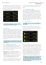
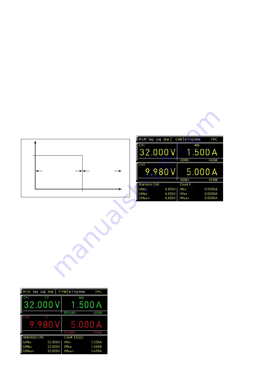
As the diagram shows, it remains true that U
OUT
= U
MAX
will remain stable as long as the output current I
OUT
< I
MAX
(voltage regulation). If the selected current value I
MAX
is
exceeded, the current control (Constant Current operating
Fig. 5.1: Current limit
U
out
U
max
Voltage regulation
I
max
Current control
I
out
mode) is applied. This means that despite an increased
load, the value I
MAX
can no longer increase. Instead, the
voltage U
OUT
will decrease the nominal value of U
MAX
.
However, the current flow remains limited to I
MAX
. If the
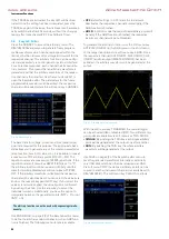
channel and the MASTER ON/OFF key are activated and
the selected channel is modified, depending on the operat-
ing mode, the display color for the activated channel will
switch from green (CV - constant voltage mode) to red (CC
- constant current mode).
5.2 Fuse
A current limit indicates that only a specific maximum
current I
max
can flow. Prior to operating an experimental
circuit, this maximum value will be selected at the power
supply; and if the fuse is triggered, the corresponding
channel will be deactivated. The intent is to prevent dam-
age to the experimental circuit in case an error occurs (e.g.
a short circuit).
To protect a connected, sensitive load even better, the
R&S®HMC804x includes an electronic fuse. The setting for
the electronic fuses can be selected via ADV key and soft
menu key FUSE. Additionally, the channel option key CH1 /
CH2 / CH3 and the soft menu key FUSE allow the selection
or deletion of fuses. With the soft menu key CHANNEL
the respective channel can be selected. The soft menu key
ACTIVATE allows you to activate or deactivate the fuses
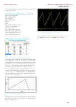
for the respective channels. If the electronic fuse has been
activated for one or more channels, the display will show a
fuse icon. If the electronic fuse has been tripped, the fuse
icon on the display is flashing red.
5.2.1 Fuse Link
The soft menu key LINKED TO allows you to logically inter-
link channels with their electronic fuses. Pressing the soft
menu key CHANNEL allows you to select or deselect indi-
vidual channels. An activated link will be displayed with an
arrow and the respective interlinked channel. If the current
for a channel exceeds the value I
MAX
and if the electronic
fuse for this channel has been activated via FUSE key (see
"Setting the Current Limit"), all channels interlinked with
this channel will be switched off. The tripped channel will
be displayed with a red flashing fuse icon. The fuse of the
interlinked channel which has also tripped will be dis-
played with a red fuse icon. If the electronic fuse is tripped,
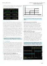
Fig. 5.3: Fuse display CH1
Fig. 5.2: Display values CV/CC R&S®HMC8042
www.allice.de
Allice Messtechnik GmbH
Содержание 3593.1006.02
Страница 2: ...www allice de Allice Messtechnik GmbH ...
Страница 3: ...71 Appendix 71 Appendix www allice de Allice Messtechnik GmbH ...
Страница 37: ...35 Anhang 35 Anhang www allice de Allice Messtechnik GmbH ...
Страница 39: ...www allice de Allice Messtechnik GmbH ...
Страница 40: ...71 Appendix 71 Appendix www allice de Allice Messtechnik GmbH ...
Страница 73: ...68 Appendix 68 Appendix www allice de Allice Messtechnik GmbH ...
Страница 74: ...69 Appendix 69 Appendix www allice de Allice Messtechnik GmbH ...
Страница 75: ...70 Appendix 70 Appendix www allice de Allice Messtechnik GmbH ...


