11
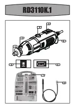
130W MINI DRILL
EN
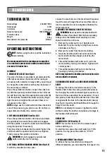
TECHNICAL DATA
220-240V~50Hz
130W
1.6~3.2mm
10000-33000/min
/II
0.6kg
Ø35mm
Rated voltage
Rated power
Collet size
Rated no load speed
Protection class
Weight
Max diameter of accessories
OPERATING INSTRUCTIONS
NOTE:
Before using the tool, read the instruction
book carefully.
We recommend that this tool always be supplied
via a residual current device with a rated residual
current of 30 mA or less.
ASSEMBLY
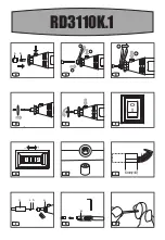
1. CHANGE THE COLLET (See Fig. A)
Two size of collets are provided to accommodate the
different accessories shank sizes. When using an
accessory with a smaller or larger shaft, you will need
to change the collet which matches the shank size of
the accessory as follows.
Press the spindle lock button. Loosen the collet nut
(A) with the spanner provided. Remove the collet nut
(A) and then fully insert the appropriate size collet (B)
into the spindle. Reinstall the collet nut (A) by finger
tight. Do not over-tighten the nut when there is no
accessory in the collet.
NOTE:
Always use the collet which matches the shank
size of the accessory you plan to use. Do not force a
larger diameter shank into a smaller collet.
2. FITTING AN ACCESSORY (See Fig. B, C)
Press the spindle lock button. Hold down and rotate
the spindle by hand until the spindle lock engages
with the spindle. Loosen the collet nut anti-clockwise
using the spanner if necessary.
Fully insert the tool shank into the collet. Tighten the
collet nut with the spanner but do not over-tighten.
Finally release the spindle lock button.
WARNING:
Do not engage the spindle lock
button while the tool is running.
3. FITTING A CUTTING/SANDING WHEEL (See Fig. D, E)
First fit the mandrel into the collet.
Loosen the small screw on the mandrel with spanner.
Insert the screw through the wheel and then screw
into the mandrel. Do not over-tighten otherwise the
wheel may crack.
4. CONNECT THE FLEXIBLE SHAFT TO THE TOOL
WARNING:
Never bend the flexible shaft with
a radius of less than 152mm when operating.
Always store the flexible shaft carefully to avoid
sharp bends when not in use.
1. Remove the collet nut (1) and Spindle Lock
Button(2) from the tool by turning them counter-
clockwise (see Fig J).
2. Remove the collet from the motor shaft (a).
3. Insert the flexible shaft inner cable (b) into the
motor shaft until the stopper (c) touches the
motor shaft.
4. Thread the flexible shaft collet nut (1) onto the
motor shaft by turning it clockwise. Tighten with
collet spanner.
5. Thread the flexible shaft nut (d) onto the tool
housing by turning it clockwise.
NOTE:
Only tighten the flexible shaft nut by hand. Do
not use pliers or spanner.
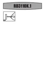
5.CHANGING THE COLLET & ACCESSORIES IN FLEXIBLE
SHAFT
To change the collet or install an accessory in the
flexible shaft, follow the same general procedure as
for changing the collet and installing accessories on
the mini drill (see assembly the accessories). To lock
the spindle, rotate the collet until the hole n the shaft
is aligned with the hole in the flexible shaft collar (a)
(See Fig K). Insert the Soft Shaft Wrench through the
holes to lock the shaft.
NOTE:
Do not attempt to loosen or tighten the collet
without locking the shaft as noted above. Damage to
the flexible shaft will result.
OPERATION
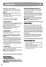
1. SWITCH ON / OFF (See Fig. F)
NOTE:
This tool has been set to the slowest speed
before switching on.
To start the tool, press the on/off switch to “I” ON
position. To stop, press the switch to “O” OFF
position.
2. SPEED ADJUSTMENT (See Fig. G)
To achieve the best result when working with
different materials, you can adjust the tool speed. It is
Содержание RD3110K.1
Страница 1: ...RD3110K 1 130W MINI DRILL EN ...
Страница 2: ...o I 4 3 2 1 5 4 1 2 6 RD3110K 1 2 3 5 1 6 4 7 8 ...
Страница 3: ...RD3110K 1 o I 1 2 a 6mm 1 4 d c b a 1 2 A B C D E F G J H I K L1 _ A B 1 2 3 ...
Страница 4: ...RD3110K 1 a d c b a J K L1 L2 ...
Страница 14: ......
Страница 15: ......
Страница 16: ...POSITEC AUSTRALIA PTY LIMITED ABN 14 101 682 357 MADE IN PRC Copyright 2018 Positec All Rights Reserved ...


