Installing the Enhanced Field Supply Kit on 200 HP to 300 HP @ 460 VAC (100 HP to 150 HP @ 230 VAC) Drives
4-3
Step 4. Remove the four (4) screws securing the OIM to the Regulator board carrier
and move the OIM to gain access to the drive’s Regulator board. It is not
necessary to remove the OIM completely, though it can be by disconnecting
the ribbon and ground connectors from the underside of the OIM. If you
disconnect the ground, note the terminal so you can correctly reconnect it
later.
Step 5. Locate Regulator board jumper J21 (FIELD SUPPLY JUMPER). See figure
2.2.
Step 6. If necessary, move Regulator board jumper J21 so that it matches the jumper
setting of the Enhanced Field Supply board (A–C or B–C).
4.3
Installing the Enhanced Field Supply Board
Step 1. Connect the drive’s wire harness to the Enhanced Field Supply board’s 581,
582, 583, F2/35 and F1/37 spade connectors. See figure 1.1 for the location
of the connectors.
Step 2. Connector S4 on the harness might have a protective connector on it. If so,
remove it. Plug the Enhanced Field Supply’s harness connector P4 into the
harness connector S4.
Step 3. Remove the four mounting screw from the back of the Enhanced Field
Supply board.
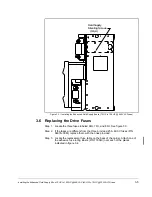
Step 4. Working from the inside of the drive, align the Enhanced Field Supply board’s
mounting holes with the mounting holes on the drive’s right side panel. See
figure 4.1.Orient this board so that the end with the transformer points to the
front of the drive.
Step 5. Working from the outside of the drive, insert one of the mounting screws
(removed in step 3) through one of the mounting holes on the drive’s right
side panel and into the corresponding mounting hole on the Enhanced Field
Supply board. Tighten the screw to just enough hold the board in place.
Step 6. Repeat step 5 for the remaining three mounting screws. Then tighten all four
screws.
4.4
Reinstalling the OIM and Its Cover
Step 1. If it was previously removed, reinstall the OIM on the Regulator board carrier.
Step 2. Reinstall the OIM cover.
4.5
Replacing the Drive Fuses
Step 1. Locate the fuse block on the drive’s line fuse panel and its three fuses
labeled 6FU, 7FU, and 8FU.
Step 2. If the installed fuses are different from the ones provided with this kit, replace
them with the provided 25 A, 600 V fuses (P/N 64676–30M).
Step 3. Reconnect power to the drive.
Step 4. Remove the lockout and tag.
Step 5. Turn on power to the drive.


