54
Rockwell Automation Publication 750-AT006D-EN-P - January 2022
Chapter 2 Product Features
y (t) is the filter output signal
k
i
are the filter coefficients
N is the number of taps and filter order
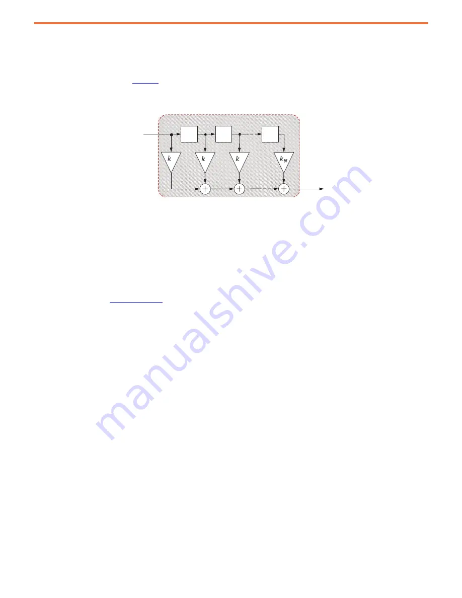
The FIR filter structure is shown in
. The top portion is referred to as the tap line and each z
-1
box represents the previous input
sample in time, or a one sample delay. Each sample is multiplied by coefficient k
i
and then summed to produce the filter output.
Figure 54 - Finite Impulse Response Filter Structure
Common FIR filter types are a moving window average filter and a discrete difference filter. A moving window average filter is applied to
smooth out high frequency impulses. A discrete difference filter is applied to generate a derivative of the input signal corresponding to the
discrete difference between two input samples that are N samples apart.
More taps filter out more noise, but reduces the overall bandwidth attainable in the velocity and position loops. Setting the number of taps to
0 disables the filter. There are two discrete difference type FIR filters in the feedback path, each with one configuration parameter to set the
number of taps.
10:1001 [Vel Fb Taps] - This parameter sets the number of taps in the FIR filter applied to the primary feedback channel.
10:1007 [Alt Vel Fb Taps] - This parameter sets the number of taps in the FIR filter applied to the alternate feedback channel.
Typical values are given in
FIR Filter
x(t)
z
-1
0
z
-1
1
z
-1
2
y(t)
…


