


5-2
Configuring a Scanner to Communicate with the Encoder
•
Highly efficient for both bandwidth and node processing
•
"Bound" connections
•
Data field contains data only
•
Meaning of data is predefined
Input data specification of the 842D
The 842D encoder is an Input Device. This means the encoder only
produces (sends) data and does not consume any data from the
master.
The 842D supports the following I/O operating modes (message
connections):
•
Polling
•
Change of State (COS) / Cyclic
•
Bit Strobed mode
All these modes can be adjusted simultaneously with different
assembly instances. To use a particular Assembly, there are installed 3
special attributes "assembly number" (Input Ass_xx) in the
manufacturer section of the encoder object. These attributes have to
be configured with the number (1...n) of the corresponding assembly
instance, containing the different data components. By default this
number is set to 1 ("Position Value").
Each of the 3 different I/O message connections is assigned its own
attribute.
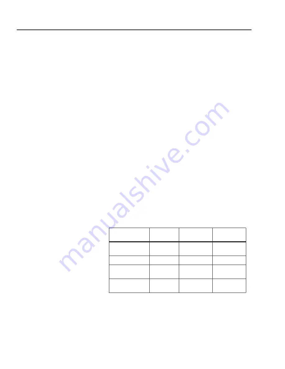
The table below shows how the different data components are used:
Update cycle time
is the time required for the encoder to calculate a
new value for one of the listed data components. For example, the
encoder is able to send new position values in intervals of approx.
0.3ms.
Note:
For all the different I/O messages applied, the number of the
configured assembly instance determines the data components to be
sent as an input data.
Data Component
Assembly
Supported
modes
Update cycle
time
Position Value
1, 2, 3, 4
COS, Strobe,
Poll
0.3 ms
Velocity Value
3
Strobe, Poll
50 ms
Flag (Alarm,
Warning)
2
COS, Strobe,
Poll
0.3 ms
Cam State
4
COS, Strobe,
Poll
0.3 ms
Содержание Allen-Bradley 842D
Страница 10: ...P 6 Using this Manual Notes...
Страница 18: ...3 4 Configuring the DeviceNet Encoder DIP Switches Notes...
Страница 56: ...I 4 Index Notes...


