60
Rockwell Automation Publication 1715-UM001J-EN-P - December 2020
Chapter 2 Installation Instructions
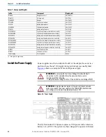
Install the Power Supply
Power supplies must be installed to the left of the adapter base unit in a
position where the 24V DC supply wiring can be kept reasonably short.
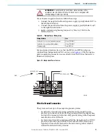
shows an example of a mounted power supply.
Figure 26 - Power Supply
The 1715 Redundant I/O System requires 24V DC power with a tolerance
between 18…32V DC. The system has been designed to operate with most
Table 7 - Component Weights
Cat. No.
Component
Weight g (oz)
1715-A2A
Adapter base unit
283 (9.98)
(1)
1715-A3IO
I/O base unit
220 (7.76)
1715-AENTR
Adapter
420 (14.82)
1715-IB16D
Digital input module
360 (12.70)
1715-IF16
Analog input module
360 (12,70)
1715-OB8DE
Digital output module
290 (10.23)
1715-OF8I
Analog output module
340 (11.99)
1715-TASIB16D
Digital input simplex termination assembly
133 (4.69)
1715-TADIB16D
Digital input duplex termination assembly
260 (9.17)
1715-TASIF16
Analog input simplex termination assembly
133 (4.69)
1715-TADIF16
Analog input duplex termination assembly
260 (9.17)
1715-TASOB8DE
Digital output simplex termination assembly
133 (4.69)
1715-TADOB8DE
Digital output duplex termination assembly
260 (9.17)
1715-TASOF8I
Analog output simplex termination assembly
133 (4.69)
1715-TADOF8I
Analog output duplex termination assembly
260 (9.17)
1715-N2S
Short blank slot filler
40 (1.41)
1715-N2T
Tall blank slot filler
50 (1.76)
Power supply
User-supplied
Varies
(1)
All weights are approximate.
ATTENTION:
To comply with the CE Low Voltage Directive (LVD), all
connections to this equipment must be powered from a source
compliant with the following:
• Safety Extra Low Voltage (SELV) or Protected Extra Low Voltage (PELV)
ATTENTION:
In high demand energize to trip and continuous demand
mode of operation the power supply for the 1715-AENTR should include
over voltage protection and supply a maximum of 32 V.
IO BASE
1715-A310
CH1
CH1
CH1
CH1
CH1
CH1
CH1
CH1
TERMINAL IDENTITY
AOTA
Dual.
CH1
CH1
CH1
CH1
CH1
CH1
CH1
CH1
TERMINAL IDENTITY
AOTA
Dual.
CH1
CH1
CH1
CH1
CH1
CH1
CH1
CH1
TERMINAL IDENTITY
AOTA
Dual.
IO BASE
1715-A310
CH1
CH1
CH1
CH1
CH1
CH1
CH1
CH1
TERMINAL IDENTITY
AOTA
Dual.
CH1
CH1
CH1
CH1
CH1
CH1
CH1
CH1
TERMINAL IDENTITY
AOTA
Dual.
CH1
CH1
CH1
CH1
CH1
CH1
CH1
CH1
TERMINAL IDENTITY
AOTA
Dual.
24-28V
DC 24-28V
DC ok
100W max.
Single use
Parallel use
Содержание Allen-Bradley 1715-AENTR
Страница 10: ...10 Rockwell Automation Publication 1715 UM001J EN P December 2020 ...
Страница 114: ...114 Rockwell Automation Publication 1715 UM001J EN P December 2020 Chapter 2 Installation Instructions Notes ...
Страница 134: ...134 Rockwell Automation Publication 1715 UM001J EN P December 2020 Chapter 4 Digital I O Operation Notes ...
Страница 200: ...200 Rockwell Automation Publication 1715 UM001J EN P December 2020 Chapter 6 Configure the Redundant I O System Notes ...
Страница 244: ...244 Rockwell Automation Publication 1715 UM001J EN P December 2020 Chapter 9 Redundant I O System Diagnostics Notes ...
Страница 272: ...272 Rockwell Automation Publication 1715 UM001J EN P December 2020 Appendix C Reconfigure a Module Online Notes ...
Страница 290: ...290 Rockwell Automation Publication 1715 UM001J EN P December 2020 Appendix G History of Changes Notes ...
Страница 296: ...296 Rockwell Automation Publication 1715 UM001J EN P December 2020 ...
Страница 297: ...Rockwell Automation Publication 1715 UM001J EN P December 2020 297 Redundant I O System User Manual ...


