


Rockwell Automation Publication 2080-UM002N-EN-E - November 2022
347
Appendix G Connect to Networks using DF1
Configure Poll Timeout
The Poll Timeout is only used when the DF1 half-duplex slave is initiating MSG instructions in
ladder logic. This implies that the Master is most likely configured for Standard Polling Mode.
The minimum Poll Timeout value is dependent on the maximum Master poll scan rate. Since
the Master’s polling and the Slave’s triggering of a MSG instruction are asynchronous events, it
is possible that in the instant just after the slave was polled, the MSG instruction gets
triggered. This means the MSG instruction will remain queued-up for transmission until the
Master has polled every other slave first. Therefore, the minimum Slave Serial port Poll
Timeout value is equal to the maximum Master poll scan rate rounded up to the next 20 ms
increment.
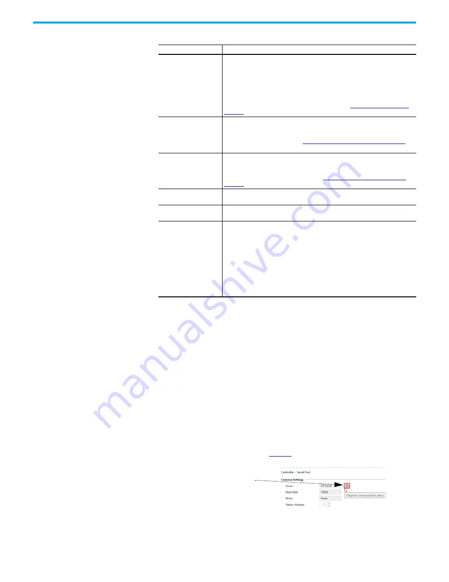
DF1 Half-Duplex Slave Communication Diagnostics
Communication diagnostics is available while connected to the controller by clicking the
Diagnose communication status button.
explains information regarding the
diagnostic counter data displayed.
Poll Timeout
The timer keeps track of how often the station is polled. If the station has a message
to send, it starts a timer.
If the poll timeout expires before the message timeout, which you specify in the MSG
control block, the MSG error bit is set and the message is removed from the transmit
queue.
If the message timeout, which you specify in the MSG control block, expires before
the poll timeout expires, the MSG error bit and MSG timeout bit are set.
The poll timeout can be disabled by entering a zero. See
for recommendations to minimize this value.
RTS Off Delay
Defines the amount of time, in 20 millisecond increments, that elapses between the
end of the message transmission and the de-assertion of the RTS signal. This time
delay is a buffer to make sure that the modem has transmitted the message, but
should normally be left at zero. See
RTS Send Delay and RTS Off Delay on page 339
for
further guidelines for setting this parameter.
RTS Send Delay
Defines the amount of time, in 20 millisecond increments, that elapses between the
assertion of the RTS signal and the beginning of the message transmission. This time
allows the modem to prepare to transmit the message. The Clear-to-Send (CTS) signal
must be high for transmission to occur. See
RTS Send Delay and RTS Off Delay on
for further guidelines for setting this parameter.
Message Retries
Defines the number of times a slave station resends its message to the master
station before the slave station declares the message undeliverable.
Pre-Transmit Delay
Defines the amount of time in 1 millisecond increments that elapses between when
the controller has a message to send and when it asserts the RTS signal.
EOT Suppression
If you want to minimize traffic on the network, you can choose to have the slave
station not send EOT packets to the master station. When EOT packets are
suppressed, the master station automatically assumes a slave station has no data to
give if the slave station does not send a message packet as a response to a poll.
A disadvantage of suppressing EOTs is that the master station cannot distinguish
between an active station that has no data to transmit and an inactive station.
A possible application for suppressing EOTs is the following: conserving power with a
radio modem because the radio transmitter does not have to power-up to transmit a
DLE EOT packet (”no data to give” packet).
To suppress EOTs, check this parameter. To have the controller send EOTs, leave this
parameter unchecked.
Table 96 - Configure a Micro800 Controller as a Slave Station (Continued)
Parameter
Selections
Minimum
S
erial Port Poll Timeout = Maximum Master
S
can Poll Rate
1. Click Diagnose communication status to bring
up the DF1 Half-Duplex Slave diagnostics.
Содержание 2080-L50E-24AWB
Страница 14: ...14 Rockwell Automation Publication 2080 UM002N EN E November 2022 Notes ...
Страница 54: ...54 Rockwell Automation Publication 2080 UM002N EN E November 2022 Chapter 4 Wire Your Controller Notes ...
Страница 128: ...128 Rockwell Automation Publication 2080 UM002N EN E November 2022 Chapter 7 Program Execution in Micro800 Notes ...
Страница 156: ...156 Rockwell Automation Publication 2080 UM002N EN E November 2022 Chapter 8 EtherNet IP Network Notes ...
Страница 198: ...198 Rockwell Automation Publication 2080 UM002N EN E November 2022 Chapter 9 Motion Control Notes ...
Страница 232: ...232 Rockwell Automation Publication 2080 UM002N EN E November 2022 Chapter 11 Controller Security Notes ...
Страница 260: ...260 Rockwell Automation Publication 2080 UM002N EN E November 2022 Chapter 12 Using microSD Cards Notes ...
Страница 266: ...266 Rockwell Automation Publication 2080 UM002N EN E November 2022 Appendix A Modbus Mapping for Micro800 Notes ...
Страница 275: ...Rockwell Automation Publication 2080 UM002N EN E November 2022 275 Appendix B Quickstarts 10 Click Finish to complete ...
Страница 332: ...332 Rockwell Automation Publication 2080 UM002N EN E November 2022 Appendix E PID Function Blocks Notes ...
Страница 352: ...352 Rockwell Automation Publication 2080 UM002N EN E November 2022 Appendix G Connect to Networks using DF1 Notes ...
Страница 388: ...388 Rockwell Automation Publication 2080 UM002N EN E November 2022 Index Notes ...