background image

2 

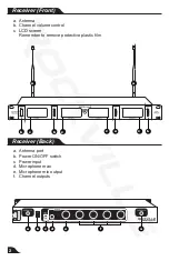
a.  Antenna

b.  Channel volume control

c.  LCD screen

Remember to remove protective plastic film

a.  Antenna port

b.  Power ON/OFF switch

c.  Power input

d.  Microphone max

e.  Microphone mix output

f.  Channel outputs

Receiver (Front)

Receiver (Back)

b

a

a

c

b

d

e

c

b

c

c

b

c

b

a

a

f

Содержание RWM4400UH

Страница 1: ...ss Microphone System OWNER S MANUAL UHF CHANNEL 1 MAX MIN CHANNEL 2 CHANNEL 3 CHANNEL 4 RWM 4400UH MAX MIN VOLUME CH 4 MAX MIN VOLUME CH 3 VOLUME CH 2 MAX MIN VOLUME CH 1 QUAD BATT ON MUTE OFF BATT ON...

Страница 2: ...ned and engineered by a team of pro audio enthusiasts We have spared no expense in manufacturing these Wireless Microphone Sys ytems to meet the highest quality standards With proper care and installa...

Страница 3: ...l Four Channel Frequency Range 520 1MHz 566MHz Frequency Stability 0 005 Modulation Mode UHF Frequency Response 50Hz 15KHz 3 dB Dynamic Range 110dB S N 90dB T H D 0 1 1KHz Audio Output Jack XLR balanc...

Страница 4: ...rol c LCD screen Remember to remove protective plastic film a Antenna port b Power ON OFF switch c Power input d Microphone max e Microphone mix output f Channel outputs Receiver Front Receiver Back b...

Страница 5: ...c Power ON OFF switch When the switch is in the middle position the microphone will be on MUTE STANDBY d Battery compartment e Color coded base for each channel f Microphone frequency sticker location...

Страница 6: ...on Connect the antenna balanced cable AF line and power supply provided The antenna should extend vertically Switch on the receiver While the receiver is in stand by switch on the microphones Adjust v...

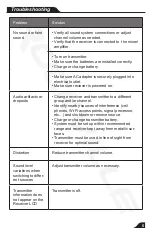
Страница 7: ...e receiver and transmitter to a different group and or channel Identify nearby sources of interference cell phones Wi Fi access points signal processor etc and shutdown or remove source Charge or chan...

Страница 8: ...2018 ROCKVILLE Features and specifications are subject to change and or improvement without notice RockvilleAudio com...

Отзывы: