background image

Page 5

WINCH OPERATION-

continue 

7. Reengage the clutch by turning the Clutch Knob till it sits to the ENGAGE position.

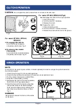
8. Place a heavy rag or carpet(not inclucded) over the wire rope span,1.8 m from the hook to help 

    absorb the force released if the wire rope breaks.

Do not allow anyone to stand near the wire rope, or in line with the wire rope behind the winch while it 

is under power. If the wire rope should slip or break, it can suddenly whip back towards the winch, 

causing a hazard for anyone in the area. Stand well aside while winching.

9.   Operate the control briefly to ensure they 

      work properly and in right direction. If 

      operation is reversed, the power cables 

      may be connected backwards. 

      Make correction before use.

10. While standing aside of the tow path, 

      press(and hold) the push button on the 

      remote control to pull the load. If the load 

      does not move, stop pulling and check for 

      obstacles blocking the load or check to 

      see if the load is too heavy for winch 

      capacity.Do not power the hook all the 

      way into the fairlead to prevent damage.

11. Do not operate the winch at extreme angle.

      Fig.12

Fig.12

CAUTION:

The winch is designed for intermittent use only, and 

should not be in a constant duty application. The duration of the pulling job should be kept as short as 

possible. If the winch motor becomes very hot to touch, stop the winch and let it cool down for several 

minutes. Never pull for more than one minute at or near the rated load. Do not maintain power to the

winch if the motor stalls as it can damage the motor or gears.
12. When pulling is complete, secure the load so it cannot move in either direction. Reverse the

      direction of the winch to release the tension on the rope so that the hook can be unfastened from 

      the load.

WARNING:

WIRELESS REMOTE CONTROL OPERATION

1.


Follow the winch wiring and operation instruction on pages in front.

2.

 Activate the Remote: 

Press and hold both IN and OUT buttons 

    on the Remote Controller simutaneously for 3 seconds till the red 

    LED on the Remote lights up and stays on.
3. 

Press “OUT" or "IN" button

 on the Remote Controller. Watch the 

    steel cable (or wire rope) feeding

 out

 or retracting 

in

 accordingly.

4. If the steel cable (or wire rope) movement does not match "OUT" or 

    "IN" action on Remote Cotrol, check and correct winch wiring. Make 

    test again after correction.

5. If Wireless Remote Control operates the winch correctly, the winch is 

    ready for use.

6. Deactivate Wireless Remote Control by pressing and holding both IN 

    and OUT button for 3 seconds simultaneously till the red LED in Remote Controller turns off.

NOTE: 

Remote Controller can automatically turn off in 2 minutes standby to save battery.

OUT

 button

IN button

Содержание RES4000 Series

Страница 1: ...5000 RES4000 series IATF TO PREVENT SERIOUS INJURY READ AND UNDERSTAND ALL WARNINGS AND INSTRUCTIONS BEFORE USE 16949 2016 ISO 9001 2015 Due to continuing improvements actual product may differ slight...

Страница 2: ...n continue Page 5 Wireless Remote Control Operation Page 5 Maintenance Service Page 6 Trouble Shooting Page 6 Specifications RP2000 REW2000 Page 7 Specifications RP3500 Page 8 Specifications RP5000 Pa...

Страница 3: ...nk or electrical wiring 14 Place towel or sandbag over wire while winch is in use Fig 1 15 Keep hands clear of wire rope hook and fairlead opening during operation Fig 2 Always use handsaving belt to...

Страница 4: ...Route the Cables from the Solenoid to the battery and from the Solenoid to the Winch following the precautions discussed earlier 4 Attach the wires from the Solenoid to the terminals on the Winch 5 A...

Страница 5: ...ontroller 8 The cable leading from the switch controller has a red wire extending out from its side Connect this to an ignition circuit switched by the vehicle s key to help prevent accidental startin...

Страница 6: ...r clockwise 3 Release the knob and let it sit in the groove NOTE If a winch is to be used to pull a vehicle it should optimally be rated to a single line pull at least twice the vehicle s weight Alway...

Страница 7: ...ng job should be kept as short as possible If the winch motor becomes very hot to touch stop the winch and let it cool down for several minutes Never pull for more than one minute at or near the rated...

Страница 8: ...ch Assy firmly to the connector Loose battery cable connection Tighten nuts on cable connectors Solenoid malfunctioning Tap Solenoid to free contact applying 12V for 12V motor or 24V for 24V motor to...

Страница 9: ...480 44 13 4 6 947 426 50 15 2 RP2000 REW2000 Rated line pull 2000lbs 907kgs single line Motor permanent magnet 12V DC input power 1 9Hp 1 4Kw Gear Ratio 153 1 Gear train Single stage planetary Brake A...

Страница 10: ...s 1589kgs single line Motor permanent magnet 12V DC input power 3 1Hp 2 3kw Gear Ratio 136 1 Gear train 3 stage planetary Brake Automatic load holding brake Power in and power out Yes Free Spooling Ye...

Страница 11: ...irlead Roller fairlead Aluminum hawse fairlead Winch dimension 15 62 x4 61 x4 72 397mmx117mmx120mm Mounting bolt pattern 3 x6 61 76mmx168mm IP rating IP66 Winch and Controls except remote switch resis...

Страница 12: ...1816 10 2 3 1 280 5 2104 955 50 15 2 Model RES4000 E16B02 E16B03 Rated line pull 4000 lbs 1815kgs single line Motor permanent magnet 12V DC input power 4 6Hp 3 4Kw Gear Ratio 242 1 Gear train 2 stage...

Страница 13: ...acket 1 4 Drum Support 1 17 Screw 2 5 Tension Plate 1 18 1 6 Lock Nut M5 2 7 Pinion Shaft 1 19 Cable Assembly with hook 5 32 x50 1 8 Cross head Screw 4 9 Bushing 1 20 Hook Strap 1 10 Gearbox Cover 1 2...

Страница 14: ...Page 12 WINCH ASSEMBLY DRAWING RP3500 RP5000 27 8 2 29 30 26 31 33 34 9 3 I N OU T 35 36 7 3 8 3 2 3 2 1 4 5 7 9 8 6 19 2 1 21 23 3 1 24 4 1 8 1 7 1 20 22 6 1 25 0 1 1 1 3 1 2 4 5 2 1 5 1 5 1 0 4 41...

Страница 15: ...ad 2 9 Tie Bar 3 29 Hook Assembly with hook 1 10 Screw M8x10 1 30 Hook Strap 1 11 Spring Washer 1 31 Electric Wire red 1 12 Circlip 3 32 Electric Wire black 1 13 Drive Shaft 1 33 Electric Wire blue 1...

Страница 16: ...Ring Gear Disc output Washer O ring Cover gearbox 4 4 1 1 4 1 1 1 1 1 1 1 1 1 1 1 1 1 19 21 22 23 24 25 26 27 28 29 30 31 32 33 34 35 36 37 Screw Connector Tie Bar O ring Spacer Screw Drum Spring clu...

Отзывы: