background image

INSTALLATION INSTRUCTIONS-
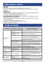
WIRING-continue

Page 3

Red

Red

Red

Red

Red

Red

Red

Red

Black

Black

Black

Black

Brown

Brown

Brown

Brown

Brown

Brown

Brown

Brown

Red

Red

Red

Red

(to

(to

(to

(to

igniti

on)

Blue

Blue

Blue

Blue

Blue

Blue

Blue

Blue

Winch

Winch

Winch

Winch

Black

Black

Black

Black

Red

Red

Red

Red

Remote

Wireless remote

         control

Solenoid

Yellow

Blue

Battery

Handlebar

remote

  Master switch

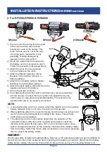
2. For RP3500,RP5000 & RES4000 

RP2000                                         RP5000                                   REW4000

1)  Plan a rout for the wiring from the point 

     of the vehicle where winch will be 

     mounted,or used to the battery. This 

     route must be secure, out of the way

     of moving parts, road devris,or any 

     possibility of being damaged by 

     operation of the vehicle.Fig.6

2)  Route the cables from the solenoid to 

     the battery and from solenoid to winch. 

     Follow the precautions discussed above.     

3)  Attach the wires from the solenoid

     to the terminals on the winch.

4)  Attach the Master Switch(or Circuit

     Breaker) to the positive terminal on 

     battery-optional.

5)  Attach the red battery cable to Master 

     Switch(or Circuit Breaker)-optional.

6)  Attach the black battery cable directly to the 

     negative terminal of the battery.

7)  Wire in the switch controller.

8)  The cable leading from the switch controller has a red wire extending 

     out from its side. Connect this to an ignition circuit(switched by the 

     vehicle’s key) to help prevent accidental starting. The winch will not 

     operate if that wire is not properly connected.


optional

(Circuit Breaker)

Fig.6

NOTE:

1)   If not attaching the winch to a vehicle, attach the ignition wire to the positive 

      battery terminal. If this is not done, the winch will not operate.

2

When attaching wires to the motor terminals, hold the inner nut with second 

      wrench to avoid the terminals from rotating in the house. This will help 

      avoid internal wire breakage.
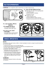
3)


The attachment of the motor cables determines the operation of the 


 controller’s button. After the unit is mounted and powered, check the

      direction of the power IN and power OUT on the controller button. If you 

      wish to change the direction on the controller, disconnect the battery cables 

      from the battery. Switch the motor cable connections on the motor assembly, 

      then reconnect the battery cables.      

WARNING: 


Fig.7

Do not use a dirty, corroded or leaking battery. Only use a 12V automotive battery in good condition.

To 

prevent serious injury from explosion due to sparking at the battery connection, disconnect the battery 

cables before making other wiring connections.To prevent serious injury from leaking battery acid.

Содержание RES4000 Series

Страница 1: ...5000 RES4000 series IATF TO PREVENT SERIOUS INJURY READ AND UNDERSTAND ALL WARNINGS AND INSTRUCTIONS BEFORE USE 16949 2016 ISO 9001 2015 Due to continuing improvements actual product may differ slight...

Страница 2: ...n continue Page 5 Wireless Remote Control Operation Page 5 Maintenance Service Page 6 Trouble Shooting Page 6 Specifications RP2000 REW2000 Page 7 Specifications RP3500 Page 8 Specifications RP5000 Pa...

Страница 3: ...nk or electrical wiring 14 Place towel or sandbag over wire while winch is in use Fig 1 15 Keep hands clear of wire rope hook and fairlead opening during operation Fig 2 Always use handsaving belt to...

Страница 4: ...Route the Cables from the Solenoid to the battery and from the Solenoid to the Winch following the precautions discussed earlier 4 Attach the wires from the Solenoid to the terminals on the Winch 5 A...

Страница 5: ...ontroller 8 The cable leading from the switch controller has a red wire extending out from its side Connect this to an ignition circuit switched by the vehicle s key to help prevent accidental startin...

Страница 6: ...r clockwise 3 Release the knob and let it sit in the groove NOTE If a winch is to be used to pull a vehicle it should optimally be rated to a single line pull at least twice the vehicle s weight Alway...

Страница 7: ...ng job should be kept as short as possible If the winch motor becomes very hot to touch stop the winch and let it cool down for several minutes Never pull for more than one minute at or near the rated...

Страница 8: ...ch Assy firmly to the connector Loose battery cable connection Tighten nuts on cable connectors Solenoid malfunctioning Tap Solenoid to free contact applying 12V for 12V motor or 24V for 24V motor to...

Страница 9: ...480 44 13 4 6 947 426 50 15 2 RP2000 REW2000 Rated line pull 2000lbs 907kgs single line Motor permanent magnet 12V DC input power 1 9Hp 1 4Kw Gear Ratio 153 1 Gear train Single stage planetary Brake A...

Страница 10: ...s 1589kgs single line Motor permanent magnet 12V DC input power 3 1Hp 2 3kw Gear Ratio 136 1 Gear train 3 stage planetary Brake Automatic load holding brake Power in and power out Yes Free Spooling Ye...

Страница 11: ...irlead Roller fairlead Aluminum hawse fairlead Winch dimension 15 62 x4 61 x4 72 397mmx117mmx120mm Mounting bolt pattern 3 x6 61 76mmx168mm IP rating IP66 Winch and Controls except remote switch resis...

Страница 12: ...1816 10 2 3 1 280 5 2104 955 50 15 2 Model RES4000 E16B02 E16B03 Rated line pull 4000 lbs 1815kgs single line Motor permanent magnet 12V DC input power 4 6Hp 3 4Kw Gear Ratio 242 1 Gear train 2 stage...

Страница 13: ...acket 1 4 Drum Support 1 17 Screw 2 5 Tension Plate 1 18 1 6 Lock Nut M5 2 7 Pinion Shaft 1 19 Cable Assembly with hook 5 32 x50 1 8 Cross head Screw 4 9 Bushing 1 20 Hook Strap 1 10 Gearbox Cover 1 2...

Страница 14: ...Page 12 WINCH ASSEMBLY DRAWING RP3500 RP5000 27 8 2 29 30 26 31 33 34 9 3 I N OU T 35 36 7 3 8 3 2 3 2 1 4 5 7 9 8 6 19 2 1 21 23 3 1 24 4 1 8 1 7 1 20 22 6 1 25 0 1 1 1 3 1 2 4 5 2 1 5 1 5 1 0 4 41...

Страница 15: ...ad 2 9 Tie Bar 3 29 Hook Assembly with hook 1 10 Screw M8x10 1 30 Hook Strap 1 11 Spring Washer 1 31 Electric Wire red 1 12 Circlip 3 32 Electric Wire black 1 13 Drive Shaft 1 33 Electric Wire blue 1...

Страница 16: ...Ring Gear Disc output Washer O ring Cover gearbox 4 4 1 1 4 1 1 1 1 1 1 1 1 1 1 1 1 1 19 21 22 23 24 25 26 27 28 29 30 31 32 33 34 35 36 37 Screw Connector Tie Bar O ring Spacer Screw Drum Spring clu...

Отзывы: