


Transport and positioning
18
2
2.3
APPLIANCE POSITIONING
Do not install inside a room
The appliance is type-approved for external installation.
Do not install inside a room, not even if it has openings.
In no event start the appliance inside a room.
GAHP-AR unit ventilation
The aerothermic appliance requires a large space, venti-
lated and free from obstacles, to enable smooth flow of
air to the finned coil and free air outlet above the mouth
of the fan, with no air recirculation.
Incorrect ventilation may affect efficiency and cause
damage to the appliance.
The manufacturer shall not be liable for any incorrect
choices of the place and setting of installation.
Where to install the appliance
▶
The appliance may be installed at ground level, on a terrace
or on a roof, compatibly with its dimensions and weight.
▶
It must be installed outside buildings, in an area of natural air
circulation, outside the dripping path of drainpipes or simi-
lar. It does not require protection from weathering.
▶
No obstruction or overhanging structure (e.g. protruding
roofs, canopies, balconies, ledges, trees) shall interfere either
with the air flowing from the top of the appliance or with the
exhaust flue gas.
▶
The appliance's flue gas exhaust must not be immediately
close to openings or air intakes of buildings, and must com-
ply with environmental regulations.
▶
Do not install near the exhaust of flues, chimneys or hot
polluted air. In order to work correctly, the appliance needs
clean air.
Defrosting water drainage
In winter, it is normal for frost to form on the finned
coil and for the appliance to perform defrosting cy-
cles.
To prevent overflowing and damage provide for a drain-
age system.
Acoustic issues
▶
Pre-emptively assess the appliance's sound effect in connec-
tion to the site, taking into account that building corners, en-
closed courtyards, restricted spaces may amplify the acous-
tic impact due to the reverberation phenomenon.
2.4
MINIMUM CLEARANCE DISTANCES
Distances from combustible or flammable materials
▶
Keep the appliance away from combustible or flammable
materials or components, in compliance with applicable
regulations.
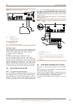
Clearances around the appliance
There must be a minimum clearance of 4 feet horizontally from
electric meters, gas meters, regulators, and relief equipment and
in no case the appliance can be located above or below these
items unless a 4 feet horizontal distance is maintained.
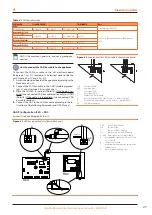
The minimum clearance distances shown in Figure 2.2
(bar any stricter regulations) are required for safety, operation
and maintenance.
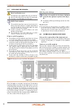
Figure 2.2
Clearances for correct installation of the appliances
single unit
multiple units
36”
18”
18”
18”
18”
18”
36”
24”
24”
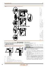
When the appliance is installed in close proximity to buildings,
keep the appliance away from the roof edge drip line. In no case
should the appliance be placed within 6 feet of any external air
intakes of the building. For installations on balconies or roofs,
the appliance should not be located within 8 feet from chimney
flues, outlets and other such vents. It is important that the ap-
pliance is located so that hot or contaminated air
IS NOT
drawn
into the air intakes of the unit (Figure 2.3
p. 19).


