


Transport and positioning
Installation, use and maintenance manual – GAHP-AR
19
2
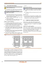
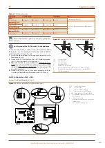
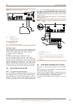
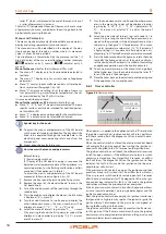
Figure 2.3
Clearances from vent outlets, chimney flues and air intake openings
Roof/Terrace installation
Ground installation
6 FT. MIN
6
FT
.
M
IN
.
8 FT. MIN
.
8 FT. MIN
.
2.5
MOUNTING BASE
Mounting base constructive features
▶
Place the appliance on a level flat surface made of fireproof
material and able to withstand its weight.
▶
Provide for a collection basin or containment rim and a dis-
charge system of the defrosting water, to avoid overflowing,
freezing and damage.
(1) - installation at ground level
▶
Failing a horizontal supporting base, make a flat and level
concrete base, with a minimum thickness of 4" and larger
than the unit base by at least 4÷6" on each side (Figure
2.4
p. 19). Local soil conditions will actually dictate the slab
thickness required to prevent shifting.
▶
Do not allow the concrete slab to touch the foundation of a
structure. Unit operational noises can be transmitted inside
the structure if they are connected.
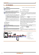
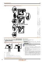
Figure 2.4
Dimenstions of the unit bed
1
4" concrete slab
1
38”
54”
(2) - installation on terrace or roof
▶
The structure of the building must support the total weight
of the appliance and the supporting base.
▶
If necessary, provide a maintenance walkway around the ap-
pliance.
▶
Although approved for installation on a combustible
base, the appliance must not be installed directly on the
roof surface. Use base supports for the installation (Figure
p. 19).
▶
Installation on roofs directly above sleeping quarters should
be avoided if possible. If not possible, special consideration
must be given to the transmission characteristics of the
building structure. The use of vibration isolators under the
equipment (acoustically insulated bases) and approved flex-
ible connections (vibration-damping pipe fittings) between
the unit and the piping system is recommended.
2.5.1
Leveling
The unit should be level both front to back and side to side. Place
a level on the top of the unit to check for level. If the unit is not
level, metal shims are recommended for use under proper cor-
ners to obtain level. If the shim(s) thickness exceeds 1/2", sup-
port shims should be inserted under the center of the unit.
Anti vibration mountings
Although the appliance's vibrations are minimal, resonance
phenomena might occur in roof or terrace installations.
▶
Ground level installations should use vibration-damping
base supports, available from the factory. Another option is
to use 4" thick concrete slabs positioned under the unit, in-
stead of the factory base supports.
▶
Also provide anti-vibration joints between the appliance
and water and gas pipes.


