background image

MD-01

WL-04

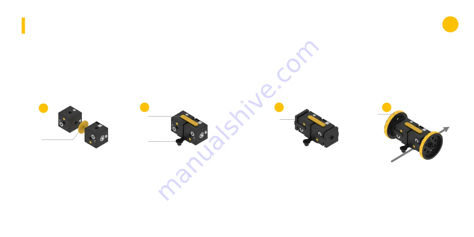
Combine the Acceleration
Gear

(MD-01

) nearby the

Cube

.

If the

Link

does not

enter well, turn the cross (+)
shape of the gear to adjust
the groove of the motor

.

Connect the Wheel

(WL-04

)

to the Acceleration Gear

.

Direction

PINGPONG G2 AUTO CAR ASSEMBLY

C2-13

C2-07

C2-08

Assemble

a

round

link(C2-

13

) according to the shape

o f f i g u r e a n d t h e
position of button

.

Combine the rod

Link (C2-08

)

on the upper side and Ball
Caster

(C2-07

)

on

the

bottom

.

1

2

3

4

PINGPONG
G SERIES  

G

Содержание PINGPONG G Series

Страница 1: ...G SERIES www roborisen com PINGPONG ROBOT G SERIES Manual Book G SERIES Manual Book PINGPONG ROBOT G SERIES G G ...

Страница 2: ...PINGPONG ROBOT G SERIES G ...

Страница 3: ...o Charging 5 Connection to Smartphone 1 G2 2 G3 3 G4 4 G6 Product Composition Robot operation App function Assembly flowchart PINGPONG ROBOT G SERIES G G SERIES www roborisen com G2 AUTO CAR ROLLING CAR WORM BOT G3 BATTLE BOT DRAWING BOT HUMAN BOT G4 CRAWING BOT DANCING BOT OMNI BOT ROBOT ARM G6 HEX BOT TWIST BOT 6 BIPED BOT ...

Страница 4: ... C2 08 WL 04 1 C2 07 Composition G3 Link only PINGPONG G SERIES G Composition G2 Link only PINGPONG G3 Link Box 1 1 C1 04 C3 02 1 1 2 2 1 1 1 1 1 C1 03 C1 05 C1 20 C1 09 C2 05 C2 15 ET 01 C2 13 C1 19 1 1 C1 02 C2 04 2 WL 04 Link 17 EA LINK LINK 2 MD 01 2 MD 01 ...

Страница 5: ... 2 1 1 1 1 1 1 2 1 4 1 2 C2 02 C2 14 C2 06 MD 08 C2 13 C4 04 MD 07 MD 06 C2 11 C4 01 MD 05 C1 12 C1 21 1 C2 15 4 MD 01 PINGPONG G6 Link Box Link 31 EA C1 12 C2 02 C2 08 C1 08 C1 15 C1 16 C1 17 C1 18 ET 12 C1 09 C1 10 C2 13 C4 03 2 4 6 2 2 2 2 2 1 1 2 2 3 LINK LINK PINGPONG G SERIES G ...

Страница 6: ...13 C2 09 C2 08 WL 04 1 C2 07 Composition G3 Full set Cube 2 EA Charging Cable Link 17 EA PINGPONG G3 Full set Cube 3 EA full full 1 1 C1 04 C3 02 1 1 2 2 1 1 1 1 1 C1 03 C1 05 C1 20 C1 09 C2 05 C2 15 ET 01 C2 13 C1 19 1 1 C1 02 C2 04 2 WL 04 Charging Cable PINGPONG G SERIES G ...

Страница 7: ...NGPONG G6 Full set Link 31 EA Cube 6 EA Charging Cable full full 1 2 1 1 1 1 1 1 2 1 4 1 2 C2 02 C2 14 C2 06 MD 08 C2 13 C4 04 MD 07 MD 06 C2 11 C4 01 MD 05 C1 12 C1 21 1 C2 15 4 MD 01 C1 12 C2 02 C2 08 C1 08 C1 15 C1 16 C1 17 C1 18 ET 12 C1 09 C1 10 C2 13 C4 03 2 4 6 2 2 2 2 2 1 1 2 2 3 PINGPONG G SERIES G ...

Страница 8: ...ule of PingPong Robot which is called Cube The button various sensors and 4 pin expansion port are built in Cube It is the framework that connects Cube and Cube which can make various shapes of Robots using a variety of Links The Links for the basic model are included in G2 G3 and G4 boxes This is a dedicated charger that can charge PingPong Robot Magnets are attached for easy connection Product I...

Страница 9: ...button once briefly when the power is off PingPong Robot is turned on Beep Click After running a Smartphone App or computer connection program if you press the button once more when the power is on PingPong Robot makes an attempt to connect with the device Click Beep Clink in 3 seconds If you press and hold the button when the power is on PingPong Robot is turned off Operation of Button PINGPONG R...

Страница 10: ...ng in white and the power turns off automatically after 5 minutes You can charge PingPong Robot using the Magnet Charging Cable built in the box When charging USB use a rated 5V 3A dedicated charger When using a USB port of laptop or PC there is a concern of terminal damage Several Cubes can be charged at a time connecting together It takes about an hour from 1 to 6 Cubes to the full charge and ta...

Страница 11: ...he assembly flow chart is at the last of the manual and there are the assembly sequences of all the robots that can be assembled in this series The shape of the upper figure should be assembled to fit the star and square so that the front and the rear are not changed when operating with a joystick Connection to Smartphone Connection to Smartphone Direction PINGPONG G SERIES G ...

Страница 12: ...ssing briefly the first Cube press the button once more to connect 8 When connected the color of first Cube turns red on the application screen 9 At the same time the LED indicator on the left Cube flickers in red Connection to Smartphone Connection to Smartphone PINGPONG G SERIES G ...

Страница 13: ...er Moving with a joystick You can control it freely by moving the joystick The PingPong Robot moves faster if you pull the joystick more The speed window on the right shows the current speed as the number of 1 100 App Operation Connection to Smartphone You can control the Auto Car by pressing the button Press the left arrow key to move in straight and press the blue circle to stop You can control ...

Страница 14: ...ed motion with the theme song of PingPong Robot Drawing the basic figure Dancing to the music It is the menu to create the desired motion and move the PingPong Robot at will After pressing and dragging the icons below you will create the motion by placing them in order in the execution area of the film shape Execution Area Motion Maker To create motion Execution Area App Operation App Operation PI...

Страница 15: ...on Motion Maker To modify motion If you press the motion icon that you want to change and move it to another place the sequence of motion ischanged Motion Maker To change the sequence and to play If you press the play button the PingPong Robot moves in the order of the icons App Operation App Operation Execution Area PINGPONG G SERIES G ...

Страница 16: ...on by pressing the trash button When deleting is completed press the trash button again to clear the delete mode Motion Maker To delete motion Robot operation and App function PINGPONG ROBOT G SERIES App Operation G G SERIES www roborisen com PingPong Robot moves according to the sequence of the icons in the execution Stopping the motion of a moving PingPong Robot Deleting unwanted motions in the ...

Страница 17: ...PINGPONG G2 AUTO CAR Links Cubes Assembly App functions PINGPONG G2 ROLLING CAR Links Cubes Assembly App functions PINGPONG G SERIES G ...

Страница 18: ...PINGPONG G2 WORM BOT Links Cubes Assembly App functions PINGPONG G3 BATTLE BOT Links Cubes Assembly App functions PINGPONG G SERIES G ...

Страница 19: ...PINGPONG G3 DRA WING BOT Links Cubes Assembly App functions PINGPONG G3 HUMAN BOT Links Cubes Assembly App functions PINGPONG G SERIES G ...

Страница 20: ...PINGPONG G4 CRA WING BOT Links Cubes Assembly App functions PINGPONG G4 OMNI BOT Links Cubes Assembly App functions PINGPONG G SERIES G ...

Страница 21: ...PINGPONG G4 ROBOT ARM Links Cubes Assembly App functions PINGPONG G4 DANCING BOT Links Cubes Assembly App functions PINGPONG G SERIES G ...

Страница 22: ...PINGPONG G6 TWIST BOT 6 Links Cubes Assembly App functions PINGPONG G6 HEX BOT Links Cubes Assembly App functions PINGPONG G SERIES G ...

Страница 23: ...embly G G SERIES www roborisen com Assembly flowchart PINGPONG ROBOT G SERIES App functions G2 AUTO CAR ROLLING CAR WORM BOT G3 BATTLE BOT DRAWING BOT HUMAN BOT G4 CRAWING BOT DANCING BOT OMNI BOT ROBOT ARM G6 HEX BOT TWIST BOT 6 BIPED BOT ...

Страница 24: ... the groove of the motor Connect the Wheel WL 04 to the Acceleration Gear Direction PINGPONG G2 AUTO CAR ASSEMBL Y C2 13 C2 07 C2 08 Assemble a round link C2 13 according to the shape o f f i g u r e a n d t h e position of button Combine the rod Link C2 08 on the upper side and Ball Caster C2 07 on the bottom 1 2 3 4 PINGPONG G SERIES G ...

Страница 25: ...be on the long side of H type Link C2 09 and combine the Second Cube on the short side Combine the Acceleration Gear MD 01 with second Cube short Link If the Link does not fit well turn the cross shape of the gear to adjust the groove of the motor MD 05 Connect the Wheel MD 05 to the Acceleration Gear 1 2 3 PINGPONG G SERIES G ...

Страница 26: ...ink C2 13 according to the shape of figure and the position of button C1 13 Before moving lay Worm bot on its side as shown in t h e p i c t u r e b e l o w Connect the Link C2 13 in the middle of Cube Connect foot Links C1 13 to two Cubes 1 2 3 4 PINGPONG G SERIES G ...

Страница 27: ...ove of the motor Inset the wheel into the Ac c ele ra t io n G ea r Combine Link C3 02 according to the shape C1 19 Attach Cube according to the position of the figure shape Attach the Link C1 19 to the bottom of the Cube Attach the Link C1 03 to both sides of the Cube Assemble the link C2 13 according to the shape of figure and the position of button C1 03 1 2 3 4 5 6 PINGPONG G SERIES G ...

Страница 28: ...utton C2 05 C2 04 ET 01 Attach the Link C2 04 under two Cubes Combine the Link ET 01 Direction C1 02 C1 20 Pen Holder WL 04 Attach the Pulley Link C1 20 and the Pen Holder Link C1 02 Insert the assembled third Cube onto the Link ET 01 Attach the Wheel WL 04 to both sides of Step 5 Cube 1 2 3 4 5 6 PINGPONG G SERIES G ...

Страница 29: ... the position of button Attach the Link C1 04 to the Cube Combine two Links C1 09 with small screws Attach the Link C2 15 to the top of the Cube Attach two Links C1 05 to be the legs on both sides Attach two Cubes to the Link C1 09 Assemble it according to the shape of button 1 2 3 4 5 PINGPONG G SERIES G ...

Страница 30: ...e a round link C2 13 according to the shape of figure and the position of button Attach two Links C2 11 to Cube C2 13 C2 11 Assemble Cube according to the shape of figure and the position of button Complete the robot 4 1 2 3 PINGPONG G SERIES G ...

Страница 31: ...4 DANCING BOT ASSEMBL Y Assemble it according to the shape of figure and the position of button C1 12 Attach leg links C1 12 to the Cube Attach both Cubes Attach two Links C2 06 to the Cube 4 1 2 3 C2 02 PINGPONG G SERIES G ...

Страница 32: ... according to the shape of figure and the position of button Attach Link C4 01 to the Cube MD 01 MD 05 Assemble four Acceleration Gears MD 01 to the Cube according to the position Attach the Wheel MD 05 to the Acceleration Gear 4 1 2 3 PINGPONG G SERIES G ...

Страница 33: ...MBL Y C1 21 MD 07 Assemble it according to the shape of figure and the position of button Attach Link MD 07 to the Cube MD 08 MD 06 Attach Link MD 08 to the Cube Attach Link MD 06 to the Cube C2 15 4 5 1 2 3 PINGPONG G SERIES G ...

Страница 34: ... C1 18 to the middle legs Assembly completed Assemble the three links C2 13 according to the shape of figure and the position of button Add two links C2 08 in front back of robot Attach two links C4 03 in between twin cubes C2 13 C4 03 C2 08 C1 15 C1 15 C1 17 C1 16 C1 16 C1 18 4 5 1 2 3 PINGPONG G SERIES G ...

Страница 35: ...ton With screws assemble square link ET 12 and leg link C1 12 to the front back and two joint links C1 09 and a square link ET 12 to the middle Assembly completed Attach combined links to the cubes Be aware of the shape of figures C2 13 ET 12 C1 12 C1 09 C1 09 C1 09 C1 09 4 1 2 3 ET 12 ET 12 ET 12 PINGPONG G SERIES G ...

Страница 36: ...C1 09 Be aware of its positions Assemble four combined links according to the shape of figure and the position of button C1 10 C1 09 1 2 Assembly completed Attach two plate links C2 03 to the front and back of the robot and two foot links C1 08 to the bottom C2 03 C1 08 4 3 PINGPONG G SERIES G ...

Страница 37: ...PINGPONG ROBOT G SERIES G SERIES www roborisen com G ...

Отзывы: