5
EN
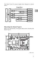
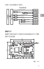
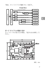
The Board Type A's power supply block diagram is shown
below.
3.3 V@250 mA
5 V@500 mA
5 V @ 2 A Communication port power supply
5~12 V @ 5 A Variable power supply output
IMU
MCU
Power output
XT30 Power supply
D-Bus + Buzzer
3.3 V Power supply to
external equipment
CAN communication port
Serial communication port
PWM power supply × 16
LM25116 12 V@10 A
MP2233
3.3 V@3 A
TPS54540
TPS54540
MP2456GJ
LP5907MFX
24 V Power output @ Max 20 A
PowerTree
3.3 V@250 mA
LP5907MFX
24 V Power input
Reverse polarity protector and
start-up protector
Mounting the Board Type A
Refer to the dimensions in the figure below when mounting the
Board Type A.
Unit: mm
64
58
32
85
4x 3.50
Содержание Development Board Type A
Страница 1: ...RoboMaster Development Board Type A 开发板 A 型 開発ボード タイプ A 2018 04 V1 2 User Guide 使用说明 ユーザーガイド ...
Страница 2: ...User Guide 2 使用说明 8 ユーザーガイド 14 EN CH JP Contents ...
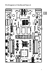
Страница 8: ...7 EN Pin Diagram of the Board Type A ...
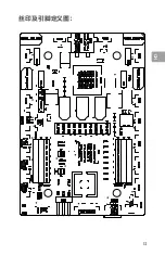
Страница 14: ...CH 13 丝印及引脚定义图 ...
Страница 20: ...JP 19 ボード タイプ A のピン配置図 ...


